Magnetic Fields and Magnetic Diagnostics for Tokamak Plasmas
Magnetic Fields and Magnetic Diagnostics for Tokamak Plasmas
Magnetic Fields and Magnetic Diagnostics for Tokamak Plasmas

Create successful ePaper yourself
Turn your PDF publications into a flip-book with our unique Google optimized e-Paper software.
<strong>Magnetic</strong> fields <strong>and</strong> tokamak plasmas<br />
Alan Wootton<br />
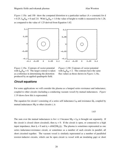
Figure 1.18a <strong>and</strong> 18b show the computed distortion to a particular surface (A = constant) <strong>for</strong> d<br />
= 0.25, I zq /I zp = 0 <strong>and</strong> 2.0. With I zq /I zp = 1.0 the value of height to width is measured to be 1.28,<br />
as compared to the value of 1.25 derived from Equation 1.62.<br />
Figure 1.18a. Contours of vector potential<br />
with I zq /I zp = 0. The larger contour is taken<br />
as a reference in determining the distortion<br />
produced by an applied quadrupole field.<br />
Figure 1.18b Contours of vector potential<br />
with I zq /I zp = 2. The contours have the same<br />
flux values as those shown in Figure 1.18a.<br />
Circuit equations<br />
For some applications we will consider the plasma as a lumped series resistance <strong>and</strong> inductance,<br />
coupled to other circuits (including a conducting vacuum vessel) by mutual inductances. Figure<br />
1.19 shows how this is represented.<br />
The equation <strong>for</strong> circuit l consisting of a series self inductance L ll <strong>and</strong> resistance Ω l , coupled by<br />
mutual inductances M li to other circuits i, is<br />
1.63<br />
The sum over the mutual inductances is <strong>for</strong> i ≠ l because M ll = L ll is brought out separately. If<br />
the circuit is closed (short circuited), then ε l = 0. If the circuit is open, or connected to a high<br />
input impedance, then I l = 0 <strong>and</strong> ε l = d/dt(ΣM l,i I i ). The plasma is sometimes represented as one<br />
series inductance-resistance circuit, or sometimes as a number of such circuits in parallel, all<br />
short circuited together. The vacuum vessel is similarly represented as a number of paralleled<br />
resistor-inductor circuits, which can be open circuit (a vessel with an insulating gap) or short<br />
28