Magnetic Fields and Magnetic Diagnostics for Tokamak Plasmas
Magnetic Fields and Magnetic Diagnostics for Tokamak Plasmas
Magnetic Fields and Magnetic Diagnostics for Tokamak Plasmas
You also want an ePaper? Increase the reach of your titles
YUMPU automatically turns print PDFs into web optimized ePapers that Google loves.
<strong>Magnetic</strong> fields <strong>and</strong> tokamak plasmas<br />
Alan Wootton<br />
5. LOOP VOLTS, VOLTS per TURN, SURFACE VOLTAGE.<br />
Introduction<br />
The Loop Volts ε l , also called the Volts per Turn or Surface Voltage, is used in calculating the<br />
Ohmic power input to the plasma. It also allows a calculation of the plasma resistivity Ω p . ε l is<br />
also a useful measure of cleanliness: clean ohmic heated tokamaks usually have ε l ~ 1.5V.<br />
What we want to measure is the resistive voltage drop across or around a plasma. In a linear<br />
machine, this simply done by measuring the potential across the end electrodes with a resistive<br />
potential divider. A similar method can be used in a torus with a conducting vacuum vessel<br />
which has one or more insulating sections. In an all metal torus the voltage induced in a single<br />
turn pickup coil (a volts per turn loop) wound close to the plasma is used, as shown in Figure 5.1.<br />
However, the interpretation of the output signal is not trivial. Here I want to address two<br />
questions. The first is “What does a toroidal loop as shown in Figure 5.1 tell me”. The second<br />
is, “How do I measure the Ohmic power input into a plasma”.<br />
The single volts per turn loop<br />
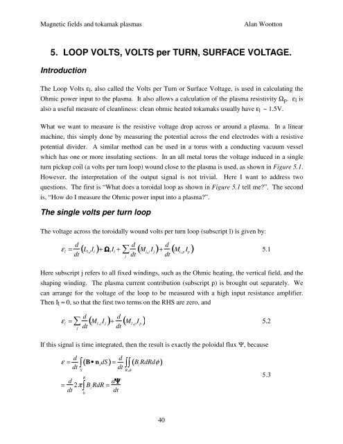
The voltage across the toroidally wound volts per turn loop (subscript l) is given by:<br />
ε l<br />
= d dt<br />
( L l ,l<br />
I l )+ Ω l<br />
I l<br />
+<br />
∑<br />
j<br />
d<br />
dt<br />
( M l, j<br />
I j ) + d dt<br />
( M l , p<br />
I p ) 5.1<br />
Here subscript j refers to all fixed windings, such as the Ohmic heating, the vertical field, <strong>and</strong> the<br />
shaping winding. The plasma current contribution (subscript p) is brought out separately. We<br />
can arrange <strong>for</strong> the voltage of the loop to be measured with a high input resistance amplifier.<br />
Then I l ≈ 0, so that the first two terms on the RHS are zero, <strong>and</strong><br />
ε l<br />
=<br />
∑<br />
j<br />
( )<br />
d<br />
dt M l , jI j<br />
+ d dt<br />
( M l , p<br />
I p ) 5.2<br />
If this signal is time integrated, then the result is exactly the poloidal flux Ψ, because<br />
ε = d dt<br />
∫<br />
S<br />
( B• n s<br />
dS)<br />
= d dt<br />
R<br />
∫<br />
= d dt 2π B z RdR<br />
0<br />
= dΨ<br />
dt<br />
∫∫<br />
R,φ<br />
( B z<br />
RdRdφ)<br />
5.3<br />
40


