

TPF-I SWG Report - Exoplanet Exploration Program - NASA
TPF-I SWG Report - Exoplanet Exploration Program - NASA
TPF-I SWG Report - Exoplanet Exploration Program - NASA

Create successful ePaper yourself
Turn your PDF publications into a flip-book with our unique Google optimized e-Paper software.
C HAPTER 4<br />
Null depth<br />
1.E+00<br />
1.E-01<br />
1.E-02<br />
1.E-03<br />
1.E-04<br />
1.E-05<br />
1.E-06<br />
1.E-07<br />
1.E-08<br />
6 8 10 12<br />
Wavelength (um)<br />
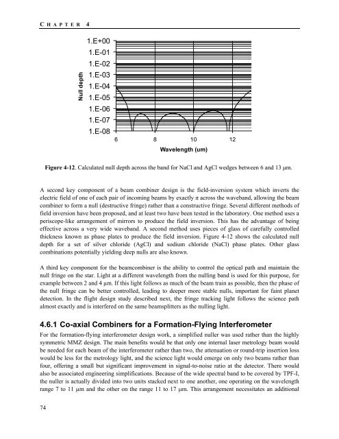
Figure 4-12. Calculated null depth across the band for NaCl and AgCl wedges between 6 and 13 μm.<br />
A second key component of a beam combiner design is the field-inversion system which inverts the<br />
electric field of one of each pair of incoming beams by exactly π across the waveband, allowing the beam<br />
combiner to form a null (destructive fringe) rather than a constructive fringe. Several different methods of<br />
field inversion have been proposed, and at least two have been tested in the laboratory. One method uses a<br />
periscope-like arrangement of mirrors to produce the field inversion. This has the advantage of being<br />
effective across a very wide waveband. A second method uses pieces of glass of carefully controlled<br />
thickness known as phase plates to produce the field inversion. Figure 4-12 shows the calculated null<br />
depth for a set of silver chloride (AgCl) and sodium chloride (NaCl) phase plates. Other glass<br />
combinations potentially yielding deep nulls are also known.<br />
A third key component for the beamcombiner is the ability to control the optical path and maintain the<br />
null fringe on the star. Light at a different wavelength from the nulling band is used for this purpose, for<br />
example between 2 and 4 μm. If this light follows as much of the beam train as possible, then the phase of<br />
the null fringe can be better controlled, leading to deeper more stable nulls, important for faint planet<br />
detection. In the flight design study described next, the fringe tracking light follows the science path<br />
almost exactly and is interfered on the same beamsplitters as the nulling light.<br />
4.6.1 Co-axial Combiners for a Formation-Flying Interferometer<br />
For the formation-flying interferometer design work, a simplified nuller was used rather than the highly<br />
symmetric MMZ design. The main benefits would be that only one internal laser metrology beam would<br />
be needed for each beam of the interferometer rather than two, the attenuation or round-trip insertion loss<br />
would be less for the metrology light, and the science light would emerge on only two beams rather than<br />
four, offering a small but significant improvement in signal-to-noise ratio at the detector. There would<br />
also be associated engineering simplifications. Because of the wide spectral band to be covered by <strong>TPF</strong>-I,<br />
the nuller is actually divided into two units stacked next to one another, one operating on the wavelength<br />
range 7 to 11 μm and the other on the range 11 to 17 μm. This arrangement necessitates an additional<br />
74


