

EDS470 - Bender
EDS470 - Bender
EDS470 - Bender

You also want an ePaper? Increase the reach of your titles
YUMPU automatically turns print PDFs into web optimized ePapers that Google loves.
4 Op erating principle of the <strong>EDS470</strong> sy stem<br />
When a first insulation fault occurs in IT systems, a fault current flows which is<br />
essentially determined by the system leakage capacitances. The basic concept in<br />
fault location is therefore to close the fault current circuit for a short period over<br />
a defined resistance. As a result of this principle, the system voltage itself drives<br />
a test current which receives a signal that can be evaluated.<br />
Caution<br />
The test current is generated periodically by the PGH471. The test current is<br />
limited in amplitude and time. As this happens, the system conductors are<br />
connected alternately to earth over a defined resistance. The test current which<br />
is generated in this manner depends on the size of the present insulation fault,<br />
and on the system voltage. It is limited to a maximum of 25 and 10 mA<br />
dependend on the setting of the PGH471 . For planning purposes, it should<br />
be noted that no system components are present in which this test current can<br />
bring about a damaging reaction, even in unfavourable cases.<br />
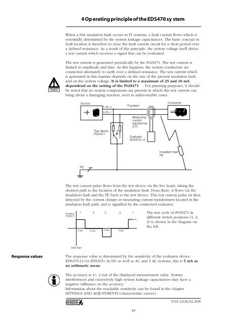
Source<br />
L1(L+)<br />
IT-system<br />
Consumer<br />
L2(L-)<br />
Test device<br />
PGH471<br />
1<br />
3<br />
2<br />
Measuring<br />
current<br />
transformer<br />
(CT)<br />
Evaluator<br />
<strong>EDS470</strong>-12<br />
Insulation fault<br />
RF<br />
PE<br />
The test current pulse flows from the test device via the live leads, taking the<br />
shortest path to the location of the insulation fault. From there, it flows via the<br />
insulation fault and the PE back to the test device. This test current pulse ist then<br />
detected by the current clamps or measuring current transformers located in the<br />
insulation fault path, and is signalled by the connected evaluator.<br />
Position<br />
PGH471<br />
1 3 2 3 1<br />
2 sec 4 sec 2 sec 4 sec<br />
The test cycle of PGH471 in<br />
different switch positions (1, 2,<br />
3) is shown in the diagram on<br />
the left.<br />
EDS Start<br />
Response values<br />
The response value is determined by the sensitivity of the evaluator device<br />
<strong>EDS470</strong>-12 (or EDS165). In DC as well as AC and 3 AC systems, this is 5 mA as<br />
an arithmetic mean.<br />
The accuracy is +/- 2 mA of the displayed measurement value. System<br />
interferences and excessively high system leakage capacitances may have a<br />
negative influence on the accuracy.<br />
Information about the reachable sensitivity can be found in the chapter<br />
SETTINGS AND ADJUSTMENTS (characteristic curves).<br />
10<br />
TGH 1243E/02.2000


