

EDS470 - Bender
EDS470 - Bender
EDS470 - Bender

You also want an ePaper? Increase the reach of your titles
YUMPU automatically turns print PDFs into web optimized ePapers that Google loves.
System c omponents<br />
<strong>EDS470</strong>-12<br />
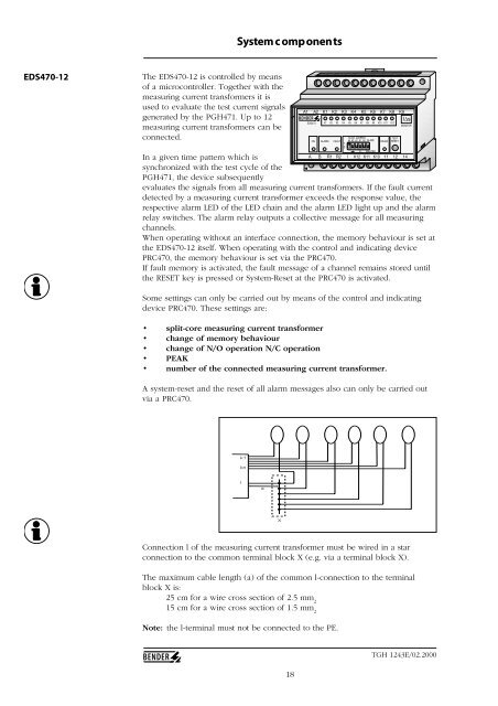
The <strong>EDS470</strong>-12 is controlled by means<br />
of a microcontroller. Together with the<br />
measuring current transformers it is<br />
used to evaluate the test current signals<br />
generated by the PGH471. Up to 12<br />
measuring current transformers can be<br />
connected.<br />
In a given time pattern which is<br />
synchronized with the test cycle of the<br />
PGH471, the device subsequently<br />
A1 A2 K1 K2 K3 K4 K5 K6 K7 K8 K9<br />
I∆s<br />
<strong>EDS470</strong> K1 K2 K3 K4 K5 K6 K7 K8 K9 K10 K11 K12<br />
MONITOR<br />
ON<br />
ALARM<br />
FAULT<br />
1<br />
0<br />
SLAVE ADDRESS<br />
A4 A3 A2 A1 A0<br />
SLAVE<br />
RS485<br />
TEST<br />
RESET<br />
R/- MASTER<br />
A B R1 R2 l K12 K11 K10 11 12 14<br />
evaluates the signals from all measuring current transformers. If the fault current<br />
detected by a measuring current transformer exceeds the response value, the<br />
respective alarm LED of the LED chain and the alarm LED light up and the alarm<br />
relay switches. The alarm relay outputs a collective message for all measuring<br />
channels.<br />
When operating without an interface connection, the memory behaviour is set at<br />
the <strong>EDS470</strong>-12 itself. When operating with the control and indicating device<br />
PRC470, the memory behaviour is set via the PRC470.<br />
If fault memory is activated, the fault message of a channel remains stored until<br />
the RESET key is pressed or System-Reset at the PRC470 is activated.<br />
Some settings can only be carried out by means of the control and indicating<br />
device PRC470. These settings are:<br />
• split-core measuring current transformer<br />
• change of memory behaviour<br />
• change of N/O operation N/C operation<br />
• PEAK<br />
• number of the connected measuring current transformer.<br />
A system-reset and the reset of all alarm messages also can only be carried out<br />
via a PRC470.<br />
k1<br />
kn<br />
l<br />
a<br />
X<br />
Connection l of the measuring current transformer must be wired in a star<br />
connection to the common terminal block X (e.g. via a terminal block X).<br />
The maximum cable length (a) of the common l-connection to the terminal<br />
block X is:<br />
25 cm for a wire cross section of 2.5 mm 2<br />
15 cm for a wire cross section of 1.5 mm 2<br />
Note: the l-terminal must not be connected to the PE.<br />
18<br />
TGH 1243E/02.2000


