

EDS470 - Bender
EDS470 - Bender
EDS470 - Bender

You also want an ePaper? Increase the reach of your titles
YUMPU automatically turns print PDFs into web optimized ePapers that Google loves.
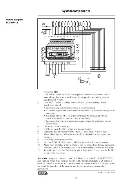
System c omponents<br />
Wiring diagram<br />
<strong>EDS470</strong>-12<br />
US<br />
8<br />
12<br />
A1 A2 k1 k2 k3 k4 k5 k6 k7 k8 k9<br />
1<br />
2<br />
3<br />
4<br />
A1 A2 K1 K2 K3 K4 K5 K6 K7 K8 K9<br />
I∆s<br />
<strong>EDS470</strong> K1 K2 K3 K4 K5 K6 K7 K8 K9 K10 K11 K12<br />
MONITOR<br />
ON<br />
ALARM<br />
FAULT<br />
1<br />
0<br />
SLAVE ADDRESS<br />
A4 A3 A2 A1 A0<br />
SLAVE<br />
RS485<br />
TEST<br />
RESET<br />
MASTER<br />
R/-<br />
A B R1 R2 l K12 K11 K10 11 12 14<br />
A B R1 R2 l k12 k11 k10<br />
7<br />
5<br />
6<br />
RS485<br />
9<br />
10<br />
11<br />
11<br />
12 14<br />
1 Power On LED<br />
2 LED ”alarm” lights up when the response value is exceeded in one or<br />
more channels test current through the respective measuring current<br />
transformer > 5 mA).<br />
3 LED ”fault” flashes if during the evaluation of a measuring current<br />
transformer signal<br />
• the measuring current transformer is short-circuited;<br />
• no measuring current transformer is connected or the connecting lead is<br />
interrupted;<br />
• a residual current of > 10 A flows through the measuring current<br />
transformer (refer to FAULT curve about that);<br />
• the measuring current transformer signal cannot be evaluated due to<br />
interferences.<br />
4 DIP switch device settings.<br />
5 LED lights up if RS485 is active and transmits data.<br />
6 Combined test and reset button. Press < 1 sec: Reset, > 2 sec: Test.<br />
7 Alarm LEDs light up when the threshold is exceeded in the respective<br />
channel.<br />
8 Measuring current transformer<br />
9 External TEST / RESET button, with the same function as button (6).<br />
10 Alarm relay switches when a channel has responded (collective message).<br />
11 Terminal block X for connections 1 of the measuring current transformers<br />
12 Short-circuit protective fuse for supply voltage (6A). Protect within the IT<br />
system with two poles.<br />
Attention: keep the common connection between terminal 1 of the <strong>EDS470</strong>-12<br />
and terminal block X as short as possible. The maximum length is 25 cm for a<br />
cross section of 2.5 mm 2 or 15 cm for a cross section of 1.5 mm 2 . If longer cables<br />
are used, the function of the current transformer monitoring cannot be<br />
guaranteed.<br />
20<br />
TGH 1243E/02.2000


