

EDS470 - Bender
EDS470 - Bender
EDS470 - Bender

You also want an ePaper? Increase the reach of your titles
YUMPU automatically turns print PDFs into web optimized ePapers that Google loves.
System c omponents<br />
Special notes for the use of the IRDH265/365-4:<br />
• Software version must be at least V. 2.5 (see nameplate);<br />
• Use contacts 11/12/14 for prewarning (alarm 1);<br />
• Use contacts 21/22/24 for starting the <strong>EDS470</strong> (alarm 2);<br />
• Operating mode alarm relay: N/O operation (corresponds to factory<br />
preset);<br />
• Coupling monitoring: active (corresponds to factory preset);<br />
• Measuring principle: AMP (corresponds to factory preset);<br />
• Set the insulation monitoring device to test mode via the terminals PT<br />
during EDS fault location (see wiring diagrams);<br />
• Fault memory OFF (remove bridge ).<br />
Special notes for the use of the IRDH265/365-3:<br />
• Software version must be at least V. 2.5 (see nameplate);<br />
• Use contacts 11/12/14 for prewarning (alarm 1);<br />
• Use contacts 21/22/24 for starting the <strong>EDS470</strong> (alarm 2);<br />
• Operating mode alarm relay: N/O operation (corresponds to factory<br />
preset);<br />
• Coupling monitoring: deactivated (no factory setting );<br />
• Measuring principle: AMP (corresponds to factory preset);<br />
• Set the insulation monitoring device to test mode via the terminals PT<br />
during EDS fault location (see wiring diagrams);<br />
• Disconnect the insulation monitoring device from the system during;<br />
<strong>EDS470</strong> fault location (see chapter ”Disconnection of the insulation<br />
monitoring device”);<br />
• Fault memory OFF (remove bridge ).<br />
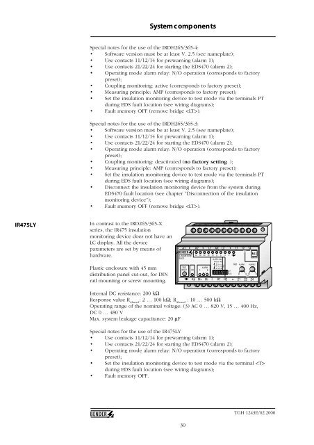
IR475LY<br />
In contrast to the IRD265/365-X<br />
series, the IR475 insulation<br />
monitoring device does not have an<br />
LC display. All the device<br />
parameters are set by means of<br />
hardware.<br />
Plastic enclosure with 45 mm<br />
distribution panel cut-out, for DIN<br />
rail mounting or screw mounting.<br />
A1 • A2 • L1 AK L2 •<br />
A-ISOMETER®<br />
IR 475<br />
TEST<br />
RESET<br />
ON<br />
KE<br />
∞<br />
60 40 20 10 8 6<br />
ALARM<br />
KK2K1<br />
K2<br />
ALARM<br />
1 2<br />
+ ~ -<br />
AL / Sys<br />
AL 1 / 2<br />
AL 2 / 1<br />
- / Res<br />
4<br />
11 12 14<br />
K1<br />
kΩ<br />
M+ M- T R1 R2 • 21 22 24<br />
2<br />
x1<br />
x10<br />
kΩ<br />
2•<br />
10 10<br />
K2<br />
MONITOR<br />
ALARM 1 ALARM 2<br />
50<br />
Internal DC resistance: 200 kΩ<br />
Response value R Alarm1<br />
: 2 … 100 kΩ; R Alarm2<br />
: 10 … 500 kΩ<br />
Operating range of the nominal voltage: (3) AC 0 … 820 V, 15 … 400 Hz,<br />
DC 0 … 480 V<br />
Max. system leakage capacitance: 20 µF<br />
Special notes for the use of the IR475LY<br />
• Use contacts 11/12/14 for prewarning (alarm 1);<br />
• Use contacts 21/22/24 for starting the <strong>EDS470</strong> (alarm 2);<br />
• Operating mode alarm relay: N/O operation (corresponds to factory<br />
preset);<br />
• Set the insulation monitoring device to test mode via the terminal <br />
during EDS fault location (see wiring diagrams);<br />
• Fault memory OFF.<br />
30<br />
TGH 1243E/02.2000


