

EDS470 - Bender
EDS470 - Bender
EDS470 - Bender

Create successful ePaper yourself
Turn your PDF publications into a flip-book with our unique Google optimized e-Paper software.
Operating principle of the <strong>EDS470</strong> sy stem<br />
FAULT curve<br />
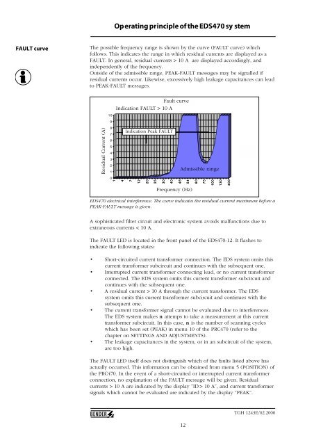
The possible frequency range is shown by the curve (FAULT curve) which<br />
follows. This indicates the range in which residual currents are displayed as a<br />
FAULT. In general, residual currents > 10 A are displayed accordingly, and<br />
independently of the frequency.<br />
Outside of the admissible range, PEAK-FAULT messages may be signalled if<br />
residual currents occur. Likewise, excessively high leakage capacitances can lead<br />
to PEAK-FAULT messages.<br />
Residual Current (A)<br />
Differenzsztrom (A)<br />
10<br />
9<br />
8<br />
7<br />
6<br />
5<br />
4<br />
3<br />
2<br />
1<br />
0<br />
Fault curve<br />
Fault-Kurve<br />
Indication FAULT > 10 A<br />
Indication Peak FAULT<br />
Admissible range<br />
1<br />
4<br />
7<br />
12<br />
20<br />
25<br />
30<br />
40<br />
46<br />
54<br />
Frequency Frequenz (Hz) (Hz)<br />
60<br />
75<br />
100<br />
130<br />
400<br />
Reihe1<br />
<strong>EDS470</strong> electrical interference. The curve indicates the residual current maximum before a<br />
PEAK-FAULT message is given.<br />
A sophisticated filter circuit and electronic system avoids malfunctions due to<br />
extraneous currents < 10 A.<br />
The FAULT LED is located in the front panel of the <strong>EDS470</strong>-12. It flashes to<br />
indicate the following states:<br />
• Short-circuited current transformer connection. The EDS system omits this<br />
current transformer subcircuit and continues with the subsequent one.<br />
• Interrupted current transformer connecting lead, or no current transformer<br />
connected. The EDS system omits this current transformer subcircuit and<br />
continues with the subsequent one.<br />
• A residual current > 10 A through the current transformer. The EDS<br />
system omits this current transformer subcircuit and continues with the<br />
subsequent one.<br />
• The current transformer signal cannot be evaluated due to interferences.<br />
The EDS system makes n attemps to take a measurement at this current<br />
transformer subcircuit. In this case, n is the number of scanning cycles<br />
which has been set (PEAK) in menu 10 of the PRC470 (refer to the<br />
chapter on SETTINGS AND ADJUSTMENTS).<br />
• The leakage capacitances in the system, or in an subcircuit of the system,<br />
are too high.<br />
The FAULT LED itself does not distinguish which of the faults listed above has<br />
actually occurred. This information can be obtained from menu 5 (POSITION) of<br />
the PRC470. In the event of a short-circuited or interrupted current transformer<br />
connection, no explanation of the FAULT message will be given. Residual<br />
currents > 10 A are indicated by the display ”ID > 10 A”, and current transformer<br />
signals which cannot be evaluated are indicated by the display ”PEAK”.<br />
12<br />
TGH 1243E/02.2000


