Electronic Relays, Relay, HMI, Control, PLCs ... - Moeller Electric Parts
Electronic Relays, Relay, HMI, Control, PLCs ... - Moeller Electric Parts
Electronic Relays, Relay, HMI, Control, PLCs ... - Moeller Electric Parts

You also want an ePaper? Increase the reach of your titles
YUMPU automatically turns print PDFs into web optimized ePapers that Google loves.
http://catalog.moeller.net <strong>Moeller</strong> HPL0211-2007/2008<br />
Technical Data<br />
Basic units<br />
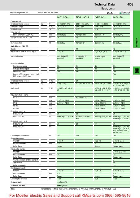
EASY512-DC-… EASY6…-DC-…E EASY7..-DC-... EASY8..-DC-...<br />
Power supply<br />
Rated operational voltage Ue V 24 DC (-15/+20%) 24 DC (-15/+20%) 24 DC (-15/+20%) 24 DC (-15/+20%)<br />
Admissible range V DC 20.4…28.8 20.4…28.8 20.4…28.8 20.4…28.8<br />
Residual ripple % F 5 F 5 F 5 F 5<br />
Input current<br />
Input current 115/230 V AC mA Normally 80 Normally 140 Normally 140 Normally 140<br />
Voltage dips (IEC/EN 61131-2) ms 10 10 10 10<br />
Heat dissipation W Normally 2 Normally 3.4 Normally 3.5 Normally 3.4<br />
Digital inputs 24 V DC<br />
Number 8 12 12 12<br />
Inputs can be used as analog inputs 2 (I7, I8) 4 (I7, I8, I11, I12) 4 (I7, I8, I11, I12)<br />
Status indication LCD display (if<br />
provided)<br />
LCD display (if<br />
provided)<br />
LCD display (if<br />
provided)<br />
Potential isolation<br />
From power supply No No No No<br />
Between digital inputs No No No No<br />
From the outputs Yes Yes Yes Yes<br />
From the PC interface, memory card<br />
NET network, EASY-Link<br />
Yes<br />
LCD display (if<br />
provided)<br />
Rated operational voltage Ue V DC 24 24 24 24<br />
On 0 signal Ue V DC < 5 (I1 – I8) < 5 (I1 – I12, R1 – R12) < 5 (I1 – I12, R1 – R12) < 5 (I1 – I6, I9, I10) < 8<br />
(I7, I8, I11, I12)<br />
On 1 signal Ue V DC > 15 (I1 – I6), > 8 (I7,<br />
I8)<br />
> 15.0 (I1 – I6, I9, I10),<br />
> 8.0 (I7, I8, I11, I12)<br />
> 15.0 (I1 – I6, I9, I10),<br />
> 8.0 (I7, I8, I11, I12)<br />
Input current on 1 signal<br />
R1 to R12 mA 3.3 (at 24 V DC)<br />
I1 to I6 mA 3.3 (at 24 V DC) 3.3 (at 24 V DC) 3.3 (at 24 V DC)<br />
I7, I8 mA 2.2 (at 24 V DC) 2.2 (at 24 V DC) 2.2 (at 24 V DC)<br />
I9, I10 mA 3.3 (at 24 V DC) 3.3 (at 24 V DC)<br />
I11, I12 mA 2.2 (at 24 V DC) 2.2 (at 24 V DC)<br />
Delay time from 0 to 1<br />
Debounce ON ms 20 20 20 20<br />
Debounce OFF ms Normally 0.25 (I1 – I8) Normally 0.25 (R1 –<br />
R12)<br />
4/53<br />
Normally 0.25 (I1 – I12) Normally 0.1 (I1 – I4),<br />
Normally 0.25 (I5 – I12)<br />
Delay time from 1 to 0<br />
Debounce ON ms 20 20 20 20<br />
Debounce OFF ms Normally 0.1 (I1 – I4),<br />
Normally 0.4 (I5, I6, I9,<br />
I12), normally 0.2 (I7,<br />
I8, I11, I12)<br />
Cable length (unscreened)<br />
Frequency counter<br />
m 100 100 100 100<br />
Quantity 2 (I3, I4) 2 (I3, I4) 2 (I1, I2, I3, I4)<br />
Counter frequency kHz < 1 < 1 < 5<br />
Pulse shape<br />
Incremental counter<br />
Square Square Square wave<br />
Quantity 2 (I1 + I2, I3 + I4)<br />
Counter frequency kHz F 1 F 1 F 3<br />
Pulse shape Square wave<br />
Counter inputs I1 and I2, I3 and I4 2<br />
Signal offset 90°<br />
Pulse pause ratio<br />
Rapid counter inputs<br />
1:1<br />
Number 2 (I1, I2) 2 (I1, I2) 4 (I1, I2, I3, I4)<br />
Counter frequency kHz < 1 < 1 < 5<br />
Pulse shape Square Square Square wave<br />
Cable length, screened m < 20 < 20 < 20<br />
<strong>Relay</strong> outputs a Page 4/62<br />
Transistor outputs a Page 4/64<br />
EASY…<br />
Notes For additional Technical Data EASY5... and EASY7... P AWB2528-1508GB, EASY8... P AWB2528-1423D<br />
For <strong>Moeller</strong> <strong>Electric</strong> Sales and Support call KMparts.com (866) 595-9616<br />
easy relay