Loke et al., 2D to 3D MOS Technology Evolution for Circuit Designers
Loke et al., 2D to 3D MOS Technology Evolution for Circuit Designers
Loke et al., 2D to 3D MOS Technology Evolution for Circuit Designers

You also want an ePaper? Increase the reach of your titles
YUMPU automatically turns print PDFs into web optimized ePapers that Google loves.
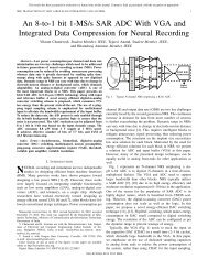
Important <strong>MOS</strong>FET Current Param<strong>et</strong>ers<br />
I D<br />
(mA)<br />
1.5<br />
1.0<br />
28nm, VDD=1.0V<br />
IDhigh<br />
IDsat<br />
V GS<br />
1.0V<br />
IDeff<br />
0.7V<br />
0.5<br />
IDlow<br />
0.5V<br />
IDlin<br />
IDoff<br />
0.0<br />
0.2V<br />
0.0 0.2 0.4 0.6 0.8 1.0<br />
V (V) DS<br />
typic<strong>al</strong> an<strong>al</strong>og usage<br />
V GS =V T <strong>to</strong> V T +0.2V<br />
IDeff estimates effective<br />
inverter current drawn<br />
during switching event,<br />
more re<strong>al</strong>istic and way<br />
less optimistic than IDsat<br />
IDlow IDhigh<br />
IDeff <br />
2<br />
VDD<br />
IDlow IDVGS<br />
, V<br />
2<br />
<br />
IDhigh IDV<br />
<br />
GS<br />
V<br />
DD<br />
, V<br />
DS<br />
DS<br />
V<br />
DD<br />
V<br />
<br />
2<br />
DD<br />
Na <strong>et</strong> <strong>al</strong>., IBM [3]<br />
<br />
<br />
<br />
<br />
<br />
<br />
© <strong>Loke</strong> <strong>et</strong> <strong>al</strong>., <strong>2D</strong> <strong>to</strong> <strong>3D</strong> <strong>MOS</strong> <strong>Technology</strong> <strong>Evolution</strong> <strong>for</strong> <strong>Circuit</strong> <strong>Designers</strong><br />
Slide 9