Balancing of a Water and Air System (PDF
Balancing of a Water and Air System (PDF
Balancing of a Water and Air System (PDF

Create successful ePaper yourself
Turn your PDF publications into a flip-book with our unique Google optimized e-Paper software.
16<br />
using the density correction.<br />
• With figure 3.2 Verify that velocity measurements are acceptable. A traverse plane is<br />
suitable for flow measurements if more than 75% <strong>of</strong> the velocity pressure readings are<br />
greater than 1/10 <strong>of</strong> the maximum velocity measurement <strong>and</strong> are not negative.<br />
• Show all traverses in the final report which will show duct size, static pressure at the<br />
traverse, velocity pressure <strong>and</strong> corresponding velocity, duct area, <strong>and</strong> the airflow. If the<br />
traverse is taken in other than st<strong>and</strong>ard conditions, show barometric pressure <strong>and</strong><br />
temperature. Show density corrections for each traverse.<br />
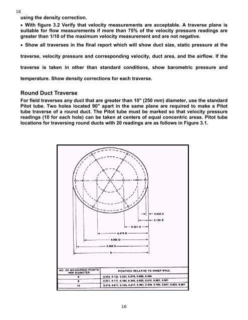
Round Duct Traverse<br />
For field traverses any duct that are greater than 10" (250 mm) diameter, use the st<strong>and</strong>ard<br />
Pitot tube. Two holes located 90" apart in the same plane are required to make a Pitot<br />
tube traverse <strong>of</strong> a round duct. The Pitot tube must be marked so that velocity pressure<br />
readings (10 for each hole) can be taken at centers <strong>of</strong> equal concentric areas. Pitot tube<br />
locations for traversing round ducts with 20 readings are as follows in Figure 3.1.<br />
16