SAWE Report - Cal Poly San Luis Obispo
SAWE Report - Cal Poly San Luis Obispo
SAWE Report - Cal Poly San Luis Obispo
You also want an ePaper? Increase the reach of your titles
YUMPU automatically turns print PDFs into web optimized ePapers that Google loves.
14.3 Fuel System<br />
Initial fuel system design began with<br />
configuration placement of fuel tanks<br />
symmetrically about the CG laterally and<br />
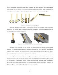
longitudinally. The two fuselage tanks (Figure<br />
14.2) serve to trim the aircraft in flight,<br />
necessary for the shift in neutral point location<br />
due to supersonic flight.<br />
Aircraft sizing began with fuel load<br />
internal volume necessary to complete the<br />
mission. The final configuration provides for<br />
Figure 14.2 - Fuel Tank Locations in Vendetta 68,000 lb (30,770 kg) of fuel to be carried<br />
within 80 %(fuselage) and 75 %(wings) volume<br />
usage tanks. All tanks in the aircraft are<br />
pressurized with nitrogen gas from the on-board inert gas generating system (OBIGGS).<br />
Pressurizing is minimal due to structural constraints and JP-8’s low vapor pressure of 0.029 psia<br />
@ 100 °F (200 Pa @ 42.3 °C). Nitrogen reduces fuel fumes and thus the chance of an accidental<br />
explosion. All tanks on the aircraft are self sealing and feature flame resistant overflow and<br />
exhaust venting.<br />
Single point fueling and de-fueling can be<br />
performed from the starboard side of the<br />
forward fuselage Figure 14.3. This fueling<br />
point shares common lines with the Air Force<br />
retractable fueling boom port (Figure 14.4)<br />
located on the upper portion of the same<br />
segment of forward fuselage. Both ports offer<br />
fueling rates as high as 1100 gpm (4164 lpm),<br />
the maximum KC-10 Fuel Probe refueling rate<br />
(Table 10.II).<br />
Fuel is then power transferred to tank three<br />
and four. From tank four it is distributed to<br />
wing tanks one and two.<br />
Figure 14.3 - Fuel System Architecture<br />
Figure 14.4 - Retractable in-flight<br />
refueling boom ports, F22, F-117, B-2<br />
92


