SAWE Report - Cal Poly San Luis Obispo
SAWE Report - Cal Poly San Luis Obispo
SAWE Report - Cal Poly San Luis Obispo
You also want an ePaper? Increase the reach of your titles
YUMPU automatically turns print PDFs into web optimized ePapers that Google loves.
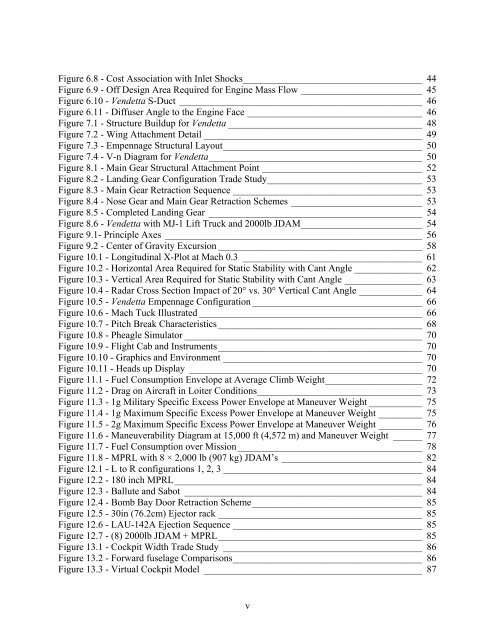
Figure 6.8 - Cost Association with Inlet Shocks_____________________________________ 44<br />
Figure 6.9 - Off Design Area Required for Engine Mass Flow _________________________ 45<br />
Figure 6.10 - Vendetta S-Duct __________________________________________________ 46<br />
Figure 6.11 - Diffuser Angle to the Engine Face ____________________________________ 46<br />
Figure 7.1 - Structure Buildup for Vendetta ________________________________________ 48<br />
Figure 7.2 - Wing Attachment Detail _____________________________________________ 49<br />
Figure 7.3 - Empennage Structural Layout_________________________________________ 50<br />
Figure 7.4 - V-n Diagram for Vendetta____________________________________________ 50<br />
Figure 8.1 - Main Gear Structural Attachment Point _________________________________ 52<br />
Figure 8.2 - Landing Gear Configuration Trade Study________________________________ 53<br />
Figure 8.3 - Main Gear Retraction Sequence _______________________________________ 53<br />
Figure 8.4 - Nose Gear and Main Gear Retraction Schemes ___________________________ 53<br />
Figure 8.5 - Completed Landing Gear ____________________________________________ 54<br />
Figure 8.6 - Vendetta with MJ-1 Lift Truck and 2000lb JDAM_________________________ 54<br />
Figure 9.1- Principle Axes _____________________________________________________ 56<br />
Figure 9.2 - Center of Gravity Excursion __________________________________________ 58<br />
Figure 10.1 - Longitudinal X-Plot at Mach 0.3 _____________________________________ 61<br />
Figure 10.2 - Horizontal Area Required for Static Stability with Cant Angle ______________ 62<br />
Figure 10.3 - Vertical Area Required for Static Stability with Cant Angle ________________ 63<br />
Figure 10.4 - Radar Cross Section Impact of 20° vs. 30° Vertical Cant Angle _____________ 64<br />
Figure 10.5 - Vendetta Empennage Configuration ___________________________________ 66<br />
Figure 10.6 - Mach Tuck Illustrated ______________________________________________ 66<br />
Figure 10.7 - Pitch Break Characteristics __________________________________________ 68<br />
Figure 10.8 - Pheagle Simulator _________________________________________________ 70<br />
Figure 10.9 - Flight Cab and Instruments __________________________________________ 70<br />
Figure 10.10 - Graphics and Environment _________________________________________ 70<br />
Figure 10.11 - Heads up Display ________________________________________________ 70<br />
Figure 11.1 - Fuel Consumption Envelope at Average Climb Weight____________________ 72<br />
Figure 11.2 - Drag on Aircraft in Loiter Conditions__________________________________ 73<br />
Figure 11.3 - 1g Military Specific Excess Power Envelope at Maneuver Weight ___________ 75<br />
Figure 11.4 - 1g Maximum Specific Excess Power Envelope at Maneuver Weight _________ 75<br />
Figure 11.5 - 2g Maximum Specific Excess Power Envelope at Maneuver Weight _________ 76<br />
Figure 11.6 - Maneuverability Diagram at 15,000 ft (4,572 m) and Maneuver Weight ______ 77<br />
Figure 11.7 - Fuel Consumption over Mission ______________________________________ 78<br />
Figure 11.8 - MPRL with 8 × 2,000 lb (907 kg) JDAM’s _____________________________ 82<br />
Figure 12.1 - L to R configurations 1, 2, 3 _________________________________________ 84<br />
Figure 12.2 - 180 inch MPRL___________________________________________________ 84<br />
Figure 12.3 - Ballute and Sabot _________________________________________________ 84<br />
Figure 12.4 - Bomb Bay Door Retraction Scheme___________________________________ 85<br />
Figure 12.5 - 30in (76.2cm) Ejector rack __________________________________________ 85<br />
Figure 12.6 - LAU-142A Ejection Sequence _______________________________________ 85<br />
Figure 12.7 - (8) 2000lb JDAM + MPRL__________________________________________ 85<br />
Figure 13.1 - Cockpit Width Trade Study _________________________________________ 86<br />
Figure 13.2 - Forward fuselage Comparisons_______________________________________ 86<br />
Figure 13.3 - Virtual Cockpit Model _____________________________________________ 87<br />
v


