

201303.pdf 36567KB Mar 22 2013 09:11:22 PM
201303.pdf 36567KB Mar 22 2013 09:11:22 PM
201303.pdf 36567KB Mar 22 2013 09:11:22 PM

Create successful ePaper yourself
Turn your PDF publications into a flip-book with our unique Google optimized e-Paper software.
V IN = 48V<br />
V OUT (V)<br />
25<br />
20<br />
15<br />
10<br />
5<br />
0<br />
80Ω<br />
42Ω<br />
OUTPUT<br />
VOLTAGE<br />
25Ω<br />
18Ω<br />
RESISTIVE 14Ω <strong>11</strong>Ω<br />
LOAD<br />
OUTPUT<br />
CURRENT<br />
8Ω<br />
300<br />
200<br />
100<br />
0<br />
OUTPUT CURRENT (mA)<br />
V IN<br />
10V TO 60V +<br />
100nF<br />
OPT.<br />
665k<br />
10k<br />
47µF<br />
V IN<br />
SW<br />
LTC3630<br />
RUN V FB<br />
FBO V PRG1<br />
I SET SS<br />
V PRG2<br />
GND<br />
100µH<br />
47nF<br />
F05<br />
V OUT<br />
5V<br />
2× <strong>22</strong>µF<br />
F04<br />
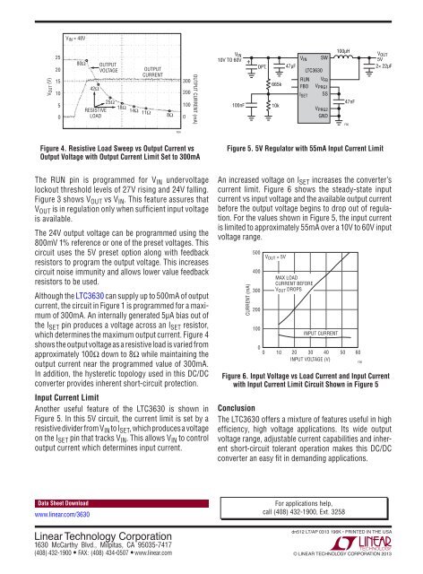
Figure 4. Resistive Load Sweep vs Output Current vs<br />
Output Voltage with Output Current Limit Set to 300mA<br />
Figure 5. 5V Regulator with 55mA Input Current Limit<br />
The RUN pin is programmed for V IN undervoltage<br />
lockout threshold levels of 27V rising and 24V falling.<br />
Figure 3 shows V OUT vs V IN . This feature assures that<br />
V OUT is in regulation only when sufficient input voltage<br />
is available.<br />
The 24V output voltage can be programmed using the<br />
800mV 1% reference or one of the preset voltages. This<br />
circuit uses the 5V preset option along with feedback<br />
resistors to program the output voltage. This increases<br />
circuit noise immunity and allows lower value feedback<br />
resistors to be used.<br />
Although the LTC3630 can supply up to 500mA of output<br />
current, the circuit in Figure 1 is programmed for a maximum<br />
of 300mA. An internally generated 5µA bias out of<br />
the I SET pin produces a voltage across an I SET resistor,<br />
which determines the maximum output current. Figure 4<br />
shows the output voltage as a resistive load is varied from<br />
approximately 100Ω down to 8Ω while maintaining the<br />
output current near the programmed value of 300mA.<br />
In addition, the hysteretic topology used in this DC/DC<br />
converter provides inherent short-circuit protection.<br />
Input Current Limit<br />
Another useful feature of the LTC3630 is shown in<br />
Figure 5. In this 5V circuit, the current limit is set by a<br />
resistive divider from V IN to I SET , which produces a voltage<br />
on the I SET pin that tracks V IN . This allows V IN to control<br />
output current which determines input current.<br />
An increased voltage on I SET increases the converter’s<br />
current limit. Figure 6 shows the steady-state input<br />
current vs input voltage and the available output current<br />
before the output voltage begins to drop out of regulation.<br />
For the values shown in Figure 5, the input current<br />
is limited to approximately 55mA over a 10V to 60V input<br />
voltage range.<br />
CURRENT (mA)<br />
500<br />
400<br />
300<br />
200<br />
100<br />
0<br />
0<br />
V OUT = 5V<br />
MAX LOAD<br />
CURRENT BEFORE<br />
V OUT DROPS<br />
INPUT CURRENT<br />
10 20 30 40 50 60<br />
INPUT VOLTAGE (V)<br />
Figure 6. Input Voltage vs Load Current and Input Current<br />
with Input Current Limit Circuit Shown in Figure 5<br />
Conclusion<br />
The LTC3630 offers a mixture of features useful in high<br />
efficiency, high voltage applications. Its wide output<br />
voltage range, adjustable current capabilities and inherent<br />
short-circuit tolerant operation makes this DC/DC<br />
converter an easy fit in demanding applications.<br />
F06<br />
Data Sheet Download<br />
www.linear.com/3630<br />
For applications help,<br />
call (408) 432-1900, Ext. 3258<br />
Linear Technology Corporation<br />
1630 McCarthy Blvd., Milpitas, CA 95035-7417<br />
(408) 432-1900 ● FAX: (408) 434-0507 ● www.linear.com<br />
dn512 LT/AP 0313 196K • PRINTED IN THE USA<br />
© LINEAR TECHNOLOGY CORPORATION <strong>2013</strong>


![[270].pdf 37407KB Sep 02 2010 09:55:57 AM - ElectronicsAndBooks](https://img.yumpu.com/50350834/1/185x260/270pdf-37407kb-sep-02-2010-095557-am-electronicsandbooks.jpg?quality=85)
![draaien, A Viruly 1935 OCR c20130324 [320]. - ElectronicsAndBooks](https://img.yumpu.com/49957773/1/190x252/draaien-a-viruly-1935-ocr-c20130324-320-electronicsandbooks.jpg?quality=85)


![20051110 c20051031 [105].pdf 35001KB Feb 18 2009 08:46:32 PM](https://img.yumpu.com/48687202/1/190x253/20051110-c20051031-105pdf-35001kb-feb-18-2009-084632-pm.jpg?quality=85)


