

201303.pdf 36567KB Mar 22 2013 09:11:22 PM
201303.pdf 36567KB Mar 22 2013 09:11:22 PM
201303.pdf 36567KB Mar 22 2013 09:11:22 PM

Create successful ePaper yourself
Turn your PDF publications into a flip-book with our unique Google optimized e-Paper software.
DC-DC converter starts up<br />
and operates from a single photocell<br />
<strong>Mar</strong>ián Štofka, Slovak University of Technology, Bratislava, Slovakia<br />
↘<br />
The bq25504 from Texas<br />
Instruments is a good candidate<br />
to become a milestone on the road to<br />
micro-power management and energy<br />
harvesting. A prominent feature of this<br />
IC is its ability to start up at a supply<br />
voltage as low as 330 mV typically, and<br />
450 mV guaranteed. With an SMD<br />
inductor and a few capacitors and resistors,<br />
it forms a dc-dc converter with a<br />
high power efficiency that is unprecedented,<br />
especially in the ultralow-power<br />
region.<br />
A possible explanation for this<br />
breakthrough in achieving an extremely<br />
low value of start-up voltage could be<br />
the use of an internal oscillator based on<br />
submicron-wide-channel FET transistors.<br />
It is known that the narrower the<br />
FET’s channel is, the lower its threshold<br />
value of gate-source voltage will be—<br />
down to a few hundred millivolts. You<br />
R OK2<br />
4M<br />
R OK3<br />
1M<br />
12<br />
NC<br />
<strong>11</strong> VBAT_OK<br />
13 14 15 16<br />
VSS VBAT VSTOR LBST<br />
AVSS<br />
10 OK_PROG<br />
9 OK_HYST<br />
VREF_SAMP 4<br />
VBAT_UV VRDIV VBAT_OV OT_PROG<br />
8 7 6 5<br />
could assume that FETs in the internal<br />
oscillator of the bq25504 have a threshold<br />
voltage on the order of 200 mV.<br />
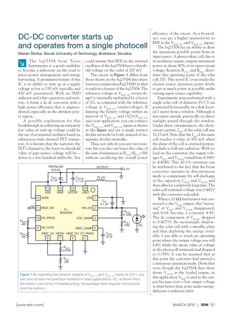
The circuit in Figure 1 differs from<br />
those shown in the bq25504 data sheet<br />
(www.ti.com/product/bq25504) in that<br />
it exploits a feature of the bq25504: The<br />
reference voltage at V BAT_OV<br />
(overvoltage)<br />
is internally multiplied by a factor<br />
of 3/2, as compared with the reference<br />
voltage at V BAT_UV<br />
(undervoltage). If<br />
limiting the battery voltage within an<br />
interval of V BAT_UV<br />
and (3/2)×V BAT_UV<br />
suits your application, you can connect<br />
the V BAT_UV<br />
and V BAT_OV<br />
inputs as shown<br />
in the figure and use a single resistor<br />
divider network for both, instead of two<br />
separate divider networks.<br />
Thus, not only do you save two resistors,<br />
but you also can lower the value of<br />
the sum of resistances as R UV1<br />
+R UV2<br />
=5M<br />
without sacrificing the overall power<br />
TANTALUM<br />
OUTPUT<br />
SOLID 4.4V<br />
C BAT<br />
47 μF<br />
+<br />
IC 1<br />
BQ25504<br />
R UV2<br />
2.67M<br />
R UV1<br />
2M<br />
C STOR<br />
4.7 μF<br />
VSS<br />
VIN_DC<br />
1<br />
2<br />
VOC_SAMP 3<br />
<strong>22</strong> μH<br />
C IN<br />
4.7 μF<br />
C REF<br />
10 nF<br />
R OC2<br />
4.12M<br />
R OC1<br />
15M<br />
Figure 1 By exploiting the inherent weights of V BAT_UV<br />
and V BAT_OV<br />
inputs as 2/3:1, you<br />
can save at least two precision resistors in many applications. (IC 1<br />
is shown from<br />
the bottom view since, if breadboarding, the package style requires connections<br />
from the bottom.)<br />
PD<br />
efficiency of the circuit. As a by-product,<br />
you get a higher insensitivity to<br />
EMI at the V BAT_UV<br />
and V BAT_OV<br />
inputs.<br />
The bq25504 has an ability to draw<br />
the maximum possible power from an<br />
input source. A photovoltaic cell, due to<br />
its nonlinear nature, outputs maximum<br />
power at about 80% of its open-circuit<br />
voltage. Resistors R OC1<br />
and R OC2<br />
determine<br />
this operating point of the solar<br />
cell, PD. This novel IC even tracks the<br />
chosen source operation point slowly<br />
to get as much power as possible under<br />
varying input source capability.<br />
Experiments were performed with a<br />
single solar cell of diameter D=7.5 cm<br />
positioned horizontally on a desk located<br />
1 meter from a window. Although it<br />
was sunny outside, practically no direct<br />
sunlight passed through the window.<br />
Under these circumstances, the shortcircuit<br />
current, I SH<br />
, of the solar cell was<br />
16.27 mA. Note that the I SH<br />
of the same<br />
cell reaches a value of 300 mA when<br />
the plane of the cell is oriented perpendicularly<br />
to full-sun radiation. With no<br />
load on the converter, the output voltages<br />
V BAT<br />
and V STOR<br />
varied from 4.396V<br />
to 4.404V. This ±0.1% variation can<br />
be attributed to the fact that the boost<br />
converter operates in discontinuous<br />
mode to compensate for self-discharge<br />
of the capacitors C BAT<br />
and C STOR<br />
and<br />
then idles for a relatively long time. The<br />
solar-cell terminal voltage was 0.441V<br />
with the converter unloaded.<br />
When a 10-kΩ load resistor was connected<br />
to the V BAT<br />
output, this “wavering”<br />
of V BAT<br />
and V STOR<br />
disappeared,<br />
and both become a constant 4.4V.<br />
The dc component of V IN_DC<br />
dropped<br />
to 0.4073V. By increasingly shadowing<br />
the solar cell with a metallic plate<br />
and thus depleting the energy available,<br />
I was able to reach an operating<br />
point where the output voltage was still<br />
4.4V, while the mean value of voltage<br />
at the photocell terminals had dropped<br />
to 0.336V. It can be assumed that at<br />
this point the converter had entered a<br />
continuous-operation mode. (Note that<br />
even though the bq25504 data sheet<br />
shows V STOR<br />
as the loaded output, in<br />
this application V BAT<br />
is used as the output<br />
because even a low output voltage<br />
is often better than none under energydeficient<br />
conditions.)EDN<br />
[ www.edn.com ] <strong>Mar</strong>ch <strong>2013</strong> | EDN 57


![[270].pdf 37407KB Sep 02 2010 09:55:57 AM - ElectronicsAndBooks](https://img.yumpu.com/50350834/1/185x260/270pdf-37407kb-sep-02-2010-095557-am-electronicsandbooks.jpg?quality=85)
![draaien, A Viruly 1935 OCR c20130324 [320]. - ElectronicsAndBooks](https://img.yumpu.com/49957773/1/190x252/draaien-a-viruly-1935-ocr-c20130324-320-electronicsandbooks.jpg?quality=85)


![20051110 c20051031 [105].pdf 35001KB Feb 18 2009 08:46:32 PM](https://img.yumpu.com/48687202/1/190x253/20051110-c20051031-105pdf-35001kb-feb-18-2009-084632-pm.jpg?quality=85)


