

201303.pdf 36567KB Mar 22 2013 09:11:22 PM
201303.pdf 36567KB Mar 22 2013 09:11:22 PM
201303.pdf 36567KB Mar 22 2013 09:11:22 PM

You also want an ePaper? Increase the reach of your titles
YUMPU automatically turns print PDFs into web optimized ePapers that Google loves.
Low-component-count zero-crossing<br />
detector is low power<br />
C Castro-Miguens and M Pérez Suárez, University of Vigo, Spain,<br />
and JB Castro-Miguens, Cesinel, Madrid, Spain<br />
↘<br />
There are many circuits published<br />
showing zero-crossing<br />
detectors for use with 50- and<br />
60-Hz power lines. Though the circuit<br />
variations are plentiful, many<br />
have shortcomings. This Design<br />
Idea shows a circuit that uses only<br />
a few commonly available parts and<br />
provides good performance with<br />
low power consumption.<br />
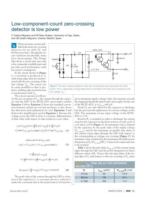
In the circuit shown in Figure<br />
1, a waveform is produced at V O<br />
with rising edges that are synchronized<br />
with the zero crossings of the<br />
line voltage, V AC<br />
. The circuit can<br />
be easily modified so that it produces<br />
a falling-edge waveform that<br />
is synchronized with V AC<br />
.<br />
The circuit operates as follows.<br />
At the zero crossings of V AC<br />
, the current through the capacitor<br />
and the LED of the HCPL-4701 optocoupler satisfies<br />
Equation 1 below. Equation 2 shows the standard conversion<br />
between radians per second and hertz; it also shows<br />
the derivation and explanation for v i<br />
(t). Equations 3 and<br />
4 show the simplification used in Equation 1. Because the<br />
voltage across the LED is close to constant, differentiation<br />
of that value with respect to time results in a zero value.<br />
i c (t)=i LED (t)=C d d<br />
[v<br />
dt i (t)–v LED ]≈C ×<br />
dt v i (t)<br />
=C× ω×<br />
V AC–PK ×cos(ωt)→i c (0)≈C×ω×V AC–PK ,<br />
where ω=2×π×f AC and<br />
v i (t) =|V AC (t)|=|V AC–PK ×sin(ωt)|.<br />
C d dt [v i (t)–v LED ]<br />
d<br />
d<br />
d<br />
=C × v<br />
dt i (t)–C dt × v LED ≈C<br />
dt × v i (t),<br />
d<br />
because C dt ×v LED≈0 (v LED ≈constant).<br />
(1)<br />
(2)<br />
(3)<br />
(4)<br />
The peak value of the current through the LED is a function<br />
of the capacitor, C, so you must choose a value for C<br />
under the constraint that at the initial time (t=0) and for a<br />
+<br />
–<br />
C<br />
I C (t)<br />
1N4007<br />
2<br />
R<br />
V V 1<br />
I (t)<br />
AC 0.25W<br />
3<br />
D 1<br />
1N4007<br />
HCPL-4701<br />
1,4,7: N.C.<br />
given minimum supply-voltage value, the intensity exceeds<br />
the triggering threshold value for the optocoupler. In the case<br />
of the HCPL-4701, it is I F(ON)<br />
=40 μA.<br />
Diode D 1<br />
not only allows for the capacitor to discharge<br />
but also prevents the application of a reverse voltage on the<br />
LED. The maximum reverse input voltage of the HCPL-<br />
4701 is 2.5V.<br />
Resistor R 1<br />
is included in order to discharge the energy<br />
stored in the capacitor in the latter portion of each cycle of<br />
v i<br />
(t) when i c<br />
(t)


![[270].pdf 37407KB Sep 02 2010 09:55:57 AM - ElectronicsAndBooks](https://img.yumpu.com/50350834/1/185x260/270pdf-37407kb-sep-02-2010-095557-am-electronicsandbooks.jpg?quality=85)
![draaien, A Viruly 1935 OCR c20130324 [320]. - ElectronicsAndBooks](https://img.yumpu.com/49957773/1/190x252/draaien-a-viruly-1935-ocr-c20130324-320-electronicsandbooks.jpg?quality=85)


![20051110 c20051031 [105].pdf 35001KB Feb 18 2009 08:46:32 PM](https://img.yumpu.com/48687202/1/190x253/20051110-c20051031-105pdf-35001kb-feb-18-2009-084632-pm.jpg?quality=85)


