Minimum Aviation System Performance Standards for Aircraft ...
Minimum Aviation System Performance Standards for Aircraft ...
Minimum Aviation System Performance Standards for Aircraft ...
You also want an ePaper? Increase the reach of your titles
YUMPU automatically turns print PDFs into web optimized ePapers that Google loves.
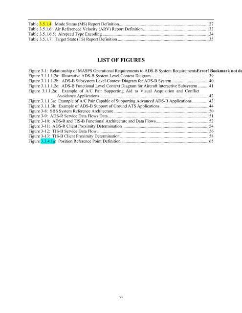
Table 3.5.1.4: Mode Status (MS) Report Definition................................................................................ 127<br />
Table 3.5.1.6: Air Referenced Velocity (ARV) Report Definition.......................................................... 133<br />
Table 3.5.1.6.5: Airspeed Type Encoding ............................................................................................... 134<br />
Table 3.5.1.7: Target State (TS) Report Definition ................................................................................. 135<br />
LIST OF FIGURES<br />
Figure 3-1: Relationship of MASPS Operational Requirements to ADS-B <strong>System</strong> RequirementsError! Bookmark not de<br />
Figure 3.1.1.1.2a: Illustrative ADS-B <strong>System</strong> Level Context Diagram..................................................... 39<br />
Figure 3.1.1.1.2b: ADS-B Subsystem Level Context Diagram <strong>for</strong> ADS-B <strong>System</strong>.................................. 40<br />
Figure 3.1.1.1.2c: ADS-B Functional Level Context Diagram <strong>for</strong> <strong>Aircraft</strong> Interactive Subsystem.......... 41<br />
Figure 3.1.1.2a: Example of A/C Pair Supporting Aid to Visual Acquisition and Conflict<br />
Avoidance Applications.................................................................................................... 42<br />
Figure 3.1.1.3a: Example of A/C Pair Capable of Supporting Advanced ADS-B Applications ............... 43<br />
Figure 3.1.1.3b: Example of ADS-B Support of Ground ATS Applications ............................................ 44<br />
Figure 3-8: SBS <strong>System</strong> Reference Architecture....................................................................................... 50<br />
Figure 3-9: ADS-R Service Data Flows Data............................................................................................ 51<br />
Figure 3-10: ADS-R and TIS-B Functional Architecture and Data Flows................................................ 52<br />
Figure 3-11: ADS-R Client Proximity Determination............................................................................... 54<br />
Figure 3-12: TIS-B Service Data Flow...................................................................................................... 56<br />
Figure 3-13: TIS-B Client Proximity Determination................................................................................. 58<br />
Figure 3.3.4.1a: Position Reference Point Definition. ............................................................................... 65<br />
vi


