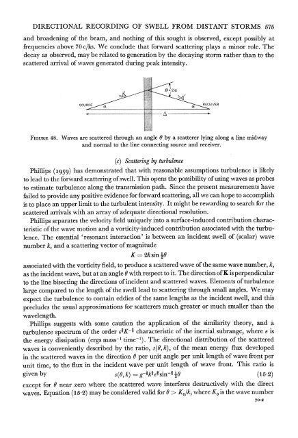
DIRECTIONAL RECORDING OF SWELL FROM DISTANT STORMS 575and broadening <strong>of</strong> the beam, and nothing <strong>of</strong> this sought is observed, except possibly atfrequencies above 70 c/ks. We conclude that forward scattering plays a minor role. Thedecay as observed, may be related to generation by the decaying storm rather than to thescattered arrival <strong>of</strong> waves generated during peak intensity.SOUR I8B- EVERFIGURE 48. Waves are scattered through an angle 0 by a scatterer lying along a line midwayand normal to the line connecting source and receiver.(c) Scattering by turbulencePhillips (I959) has demonstrated that with reasonable assumptions turbulence is likelyto lead to the forward scattering <strong>of</strong> swell. This opens the possibility <strong>of</strong> using waves as probesto estimate turbulence along the transmission path. Since the present measurements havefailed to provide any positive evidence for forward scattering, all we can hope to accomplishis to place an upper limit to the turbulent intensity. It might be rewarding to search for thescattered arrivals with an array <strong>of</strong> adequate directional resolution.Phillips separates the velocity field uniquely into a surface-induced contribution characteristic<strong>of</strong> the wave motion and a vorticity-induced contribution associated with the turbulence.The essential 'resonant interaction' is between an incident swell <strong>of</strong> (scalar) wavenumber k, and a scattering vector <strong>of</strong> magnitudeK 2k sin loassociated with the vorticity field, to produce a scattered wave <strong>of</strong> the same wave number, k,as the incident wave, but at an angle 0 with respect to it. The direction <strong>of</strong> K is perpendicularto the line bisecting the directions <strong>of</strong> incident and scattered waves. Elements <strong>of</strong> turbulencelarge compared to the length <strong>of</strong> the swell lead to scattering through small angles. We mayexpect the turbulence to contain eddies <strong>of</strong> the same lengths as the incident swell, and thisprecludes the usual approximations for scatterers much greater or much smaller than thewavelength.Phillips suggests with some caution the application <strong>of</strong> the similarity theory, and aturbulence spectrum <strong>of</strong> the order e*K* characteristic <strong>of</strong> the inertial subrange, where e isthe energy dissipation (ergs mass-1 time-l). The directional distribution <strong>of</strong> the scatteredwaves is conveniently described by the ratio, s(O, k), <strong>of</strong> the mean energy flux developedin the scattered waves in the direction 0 per unit angle per unit length <strong>of</strong> wave front perunit time, to the flux in the incident wave per unit length <strong>of</strong> wave front. This ratio isgiven by s(O,k) =gikte~sin14O (15.2)except for 0 near zero where the scattered wave interferes destructively with the directwaves. Equation (15i2) may be considered valid for 8 > I(0/k, where Ko is the wave number70-2
576 W. H. MUNK, G. R. MILLER, F. E. SNODGRASS AND N. F. BARBERassociated with the energy-containing components <strong>of</strong> the turbulence. The total scatteredenergy is <strong>of</strong> the ordery(k) = 2 f s(8, k) dO 30g-1k0J. (15.3)On the basis <strong>of</strong> some diffusion experiments by Stommel, Phillips suggests e -0-5 cm2 S-3,and this leads to y = 0-O2 per day for waves <strong>of</strong> frequency 50 c/ks. These waves have a groupvelocity <strong>of</strong> 120 latitude per day, and so cross the trade wind belt in 2 days. Total traveltimes are 10 days. Thus 400 or 200 <strong>of</strong> the energy is scattered, depending upon whether weconsider scattering in the trades only, or along the entire transmission path. In the lattercase, 80 % <strong>of</strong> the energy comes along the great circle route, 20 % is scattered and most <strong>of</strong> thisthrough small angles, with a root-mean-square value estimated at 60?. The correspondingangle for the total field, direct plus scattered, is then 12?, and the associated delay, t- t',is 1 h according to (15.1). This amount <strong>of</strong> forward scattering would then go unnoticed.But the waves are scattered in the surface layers where the value <strong>of</strong> 6 might be an order <strong>of</strong>magnitude above average, and the scattering would then bejust below the limits <strong>of</strong> detectionwith the existing angular resolution <strong>of</strong> our array.(d) Island scatteringtNumerous island groups are in the path <strong>of</strong> the swell (figures 49 and 50). Typically theseare atolls many times larger than the wave lengths here under consideration. A representativeslope <strong>from</strong> the surface to several hundred fathoms is 260. With this slope the waterdepth reaches half the wavelength at a distance <strong>of</strong> 1P03 wavelengths <strong>from</strong> the shore line. Thesteep slope suggests effective reflexion <strong>of</strong> the low frequencies, and forward scattering at thesteep sides. Where the islands are dense, multiple reflexion may contribute to small anglescattering. Forward scattering leads to a broadening <strong>of</strong> the beam and a spreading <strong>of</strong> thedispersive spectral peaks.The simplest theoretical construction is to compute the fractional shadow cast by theislands for waves <strong>from</strong> various directions (figure 51). On this basis the arrival <strong>of</strong> swell <strong>from</strong>the Indian Ocean is confined to two narrow windows. The window south <strong>of</strong> New Zealandis also limited by pack ice.The shadow method assumes total absorption (by breaking) whenever the wave frontsintersect land, and total penetration otherwise. Reflexion and diffraction are then neglected.We shall consider these processes.Geometric optics. In the case <strong>of</strong> specular reflexion <strong>from</strong> a smooth, cylindrical island <strong>of</strong>radius a > A, the ratio <strong>of</strong> reflected to incident power (as in equation 15.2) is given bys(O, k) == ar2(k) sin 101, (15.4)where r2(k) is the energy reflectivity (assumed independent <strong>of</strong> incidence angle). There isno forward reflexion, s(0, k) 0, and a maximum backward reflexion s(ir, k) =-ar2. Thetotal reflected and absorbed power per unit frequency band arerespectively. 2ar2, 2a(1-r2) (15.5)t We are indebted to George Hess for the calculations in this section.
- Page 1 and 2:
Directional Recording of Swell from
- Page 3 and 4:
506 W. H. MUNK, G. R. MILLER, F. E.
- Page 5 and 6:
508 W. H. MUNK, G. R. MILLER, F. E.
- Page 7 and 8:
510 W. H. MUNK, G. R. MILLER, F. E.
- Page 9 and 10:
512 W. H. MUNK, G. R. MILLER, F. E.
- Page 11 and 12:
514 W. H. MUNK, G. R. MILLER, F. E.
- Page 13 and 14:
516 W. H. MUNK, G. R. MILLER, F. E.
- Page 15 and 16:
518 W. H. MUNK, G. R. MILLER, F. E.
- Page 17 and 18:
520 W. H. MUNK, G. R. MILLER, F. E.
- Page 19 and 20:
522 W. H. MUNK, G. R. MILLER, F. E.
- Page 21 and 22: 524 W. H. MUNK, G. R. MILLER, F. E.
- Page 23 and 24: 526 W. H. MUNK, G. R. MILLER, F. E.
- Page 25 and 26: 528 W. H-. MUNK, G. R. MILLER, F. E
- Page 27 and 28: 530 W. H. MUNK, G. R. MILLER, F. E.
- Page 29 and 30: 532 W. H. MUNK, G. R. MILLER, F. E.
- Page 31 and 32: 534 W. H. MUNK, G. R. MILLER, F. E.
- Page 33 and 34: 00207'-0.C-0-01~~~~~~~~~~~~~~~~~~~~
- Page 35 and 36: 538714Cld0,9~~~~~~~U0CldCIO.0a.)a.)
- Page 37 and 38: 540 W. H. MUNK, G. R. MILLER, F. E.
- Page 39 and 40: 542 W. H. MUNK, G. R. MILLER, F. E.
- Page 41 and 42: 544 W. H. MUNK, G. R. MILLER, F. E.
- Page 43 and 44: 546 W. H. MUNK, G. R. MILLER, F. E.
- Page 45 and 46: 548 W. H. MUNK, G. R. MILLER, F. E.
- Page 47 and 48: 550 W. H. MUNK, G. R. MILLER, F. E.
- Page 49 and 50: 140? 1300 1200 1100 1000 900 80016t
- Page 51 and 52: ;554 W. H. MUNK, G. R. MILLER, F. E
- Page 53 and 54: 556 W. H. MUNK, G. R. MILLER, F. E.
- Page 55 and 56: 558 W. H. MUNK, G. R. MILLER, F. E.
- Page 57 and 58: 560 W. H. MUNK, G. R. MILLER, F. E.
- Page 59 and 60: 562 W. H. MUNK, G. R. MILLER, F. E.
- Page 61 and 62: 564 W. H. MUNK, G. R. MILLER, F. E.
- Page 63 and 64: 566 W. H. MUNK, G. R. MILLER, F. E.
- Page 65 and 66: 568 W. H. MUNK, G. R. MILLER, F. E.
- Page 67 and 68: 570 W. H. MUNK, G. R. MILLER, F. E.
- Page 69 and 70: 572 W. H. MUNK, G. R. MILLER, F. E.
- Page 71: 574 W. H. MUNK, G. R. MILLER, F. E.
- Page 75: 578 W. H. MUNK, G. R. MILLER, F. E.
- Page 78 and 79: Munk et al. Phil. Trans A, volume 2
- Page 80 and 81: 582 W. H. MUNK, G. R. MILLER, F. E.
- Page 82: 584 W. H. MUNK, G. R. MILLER, F. E.