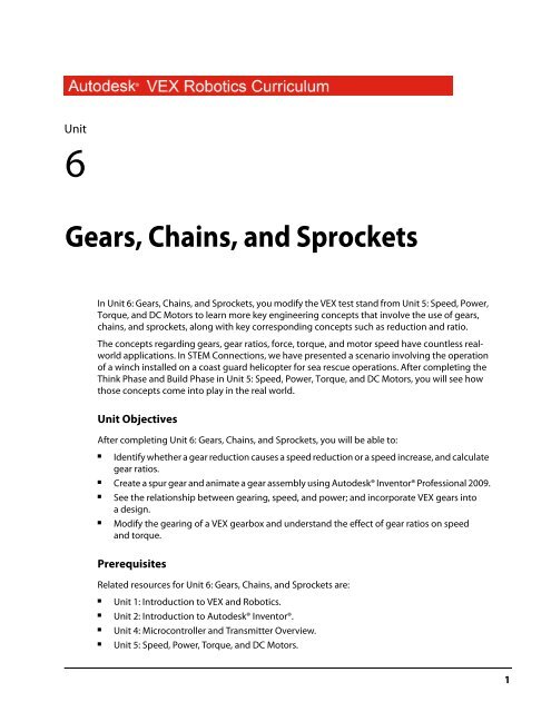
Gears, Chains, and Sprockets - VEX Robotics
Gears, Chains, and Sprockets - VEX Robotics
Gears, Chains, and Sprockets - VEX Robotics

Create successful ePaper yourself
Turn your PDF publications into a flip-book with our unique Google optimized e-Paper software.
SuppliesSoftwareAn assembled the gear ratio test st<strong>and</strong> from the Unit 6: <strong>Gears</strong>,<strong>Chains</strong>, <strong>and</strong> <strong>Sprockets</strong> > Build Phase.Small storage container for loose partsWork surface5 lb. weightA surface (for example, a table or desk) with an edge at least 24”above the groundOne stopwatch<strong>VEX</strong> PartsThe following <strong>VEX</strong> parts are used in Unit 6: <strong>Gears</strong>, <strong>Chains</strong>, <strong>and</strong> <strong>Sprockets</strong> > Build Phase:Quantity Part Number Abbreviations5 BEARING-FLAT BF10 NUT-832-KEPS NK10 SCREW-832-0500 S42 SHAFT-3000 SQ32 SHAFT-COLLAR COL1 SPACER-THICK SP21 SPACER-THIN SP11 <strong>VEX</strong>-12-TOOTH-GEAR G121 <strong>VEX</strong>-84-TOOTH-GEAR G842 WASHER-DELRIN WP<strong>VEX</strong> PartsThe following <strong>VEX</strong> parts are used in Unit 6: <strong>Gears</strong>, <strong>Chains</strong>, <strong>and</strong> <strong>Sprockets</strong> > Amaze Phase:Quantity Part Number Abbreviations1 <strong>VEX</strong>-36-TOOTH-GEAR G361 <strong>VEX</strong>-60-TOOTH-GEAR G60■3
Academic St<strong>and</strong>ardsThe following national st<strong>and</strong>ards are supported in Unit 6: <strong>Gears</strong>, <strong>Chains</strong>, <strong>and</strong> <strong>Sprockets</strong>.PhaseThinkCreateSt<strong>and</strong>ardScience (NSES)Unifying Concepts <strong>and</strong> Processes: Form <strong>and</strong> FunctionPhysical Science: Motion <strong>and</strong> ForcesScience <strong>and</strong> Technology: Abilities of Technological DesignTechnology (ITEA)5.8: The Attributes of DesignMathematics (NCTM)ConnectionsRecognize <strong>and</strong> apply mathematics in contexts outside of mathematics.AlgebraAnalyze change in various contexts.MeasurementUnderst<strong>and</strong> measurable attributes of objects <strong>and</strong> the units, systems, <strong>and</strong> processes ofmeasurement.CommunicationCommunicate mathematical thinking coherently <strong>and</strong> clearly to peers, teachers, <strong>and</strong>others.Science (NSES)Unifying Concepts <strong>and</strong> Processes: Form <strong>and</strong> FunctionPhysical Science: Motions <strong>and</strong> ForcesScience <strong>and</strong> Technology: Abilities of Technological DesignTechnology (ITEA)5.8: The Attributes of Design5.9: Engineering Design6.12: Use <strong>and</strong> Maintain Technological Products <strong>and</strong> SystemsMathematics (NCTM)Numbers <strong>and</strong> OperationsUnderst<strong>and</strong> numbers, ways of representing numbers, relationships among numbers,<strong>and</strong> number systems.Algebra St<strong>and</strong>ardUnderst<strong>and</strong> patterns, relations, <strong>and</strong> functions.Geometry St<strong>and</strong>ardUse visualization, spatial reasoning, <strong>and</strong> geometric modeling to solve problems.Measurement St<strong>and</strong>ardUnderst<strong>and</strong> measurable attributes of objects <strong>and</strong> the units, systems, <strong>and</strong> processes ofmeasurement.4■Unit 6: <strong>Gears</strong>, <strong>Chains</strong>, <strong>and</strong> <strong>Sprockets</strong>
PhaseBuildSt<strong>and</strong>ardScience (NSES)Unifying Concepts <strong>and</strong> Processes: Form <strong>and</strong> FunctionPhysical Science: Motion <strong>and</strong> ForcesScience <strong>and</strong> Technology: Abilities of Technological DesignTechnology (ITEA)5.8: The Attributes of Design5.9: Engineering Design6.11: Apply the Design ProcessMathematics (NCTM)ConnectionsRecognize <strong>and</strong> apply mathematics in contexts outside of mathematics.Numbers <strong>and</strong> OperationsCompute fluently <strong>and</strong> make reasonable estimates.AlgebraAnalyze change in various contexts.GeometryUse visualization, spatial reasoning, <strong>and</strong> geometric modeling to solve problems.MeasurementUnderst<strong>and</strong> measurable attributes of objects <strong>and</strong> the units, systems, <strong>and</strong> processes ofmeasurement.Apply appropriate techniques, tools, <strong>and</strong> formulas to determine measurements.■5
PhaseAmazeSt<strong>and</strong>ardScience (NSES)Unifying Concepts <strong>and</strong> Processes: Form <strong>and</strong> FunctionPhysical Science: Motion <strong>and</strong> ForcesScience <strong>and</strong> Technology: Abilities of Technological DesignTechnology (ITEA)5.8: The Attributes of DesignMathematics (NCTM)ConnectionsRecognize <strong>and</strong> apply mathematics in contexts outside of mathematics.Numbers <strong>and</strong> OperationsCompute fluently <strong>and</strong> make reasonable estimates.AlgebraAnalyze change in various contexts.GeometryUse visualization, spatial reasoning, <strong>and</strong> geometric modeling to solve problems.MeasurementUnderst<strong>and</strong> measurable attributes of objects <strong>and</strong> the units, systems, <strong>and</strong> processes ofmeasurement.Apply appropriate techniques, tools, <strong>and</strong> formulas to determine measurements.CommunicationCommunicate mathematical thinking coherently <strong>and</strong> clearly to peers, teachers, <strong>and</strong>others.6■Unit 6: <strong>Gears</strong>, <strong>Chains</strong>, <strong>and</strong> <strong>Sprockets</strong>
Think PhaseOverviewThis phase explains some of the fundamental concepts of gearing. It also covers the differencesbetween spur gears <strong>and</strong> setups involving sprockets <strong>and</strong> chain.Phase ObjectivesAfter completing this phase, you will be able to:■■■Identify whether a set of gears causes a speed reduction or a speed increase.Calculate gear ratios <strong>and</strong> their corresponding speed reduction or increase.Determine the direction an output shaft will rotate based on a known input.PrerequisitesRelated phase resources are:■■Unit 1: Introduction to <strong>VEX</strong> <strong>and</strong> <strong>Robotics</strong>.Unit 5: Speed, Power, Torque, <strong>and</strong> DC Motors.Required Supplies <strong>and</strong> SoftwareThe following supplies are used in this phase:SuppliesNotebook <strong>and</strong> penWork surfaceThink Phase■7
Research <strong>and</strong> ActivityIntroduction to <strong>Gears</strong>As learned in Unit 5: Speed, Power, Torque, <strong>and</strong> DC Motors, a motor can generate a set amount ofpower; that is, it can provide a specific amount of energy every second. Since there is only so muchenergy to go around, <strong>and</strong> energy is the product of torque <strong>and</strong> speed, there is an inherent trade-offbetween torque <strong>and</strong> speed.In many cases, the motor output characteristics do not match the motor application. For example, amotor that is very fast but has only a little bit of torque might not be suitable to lift a heavy load. Inthese cases, it is necessary to use gear ratios to change the outputs to a more appropriate balance oftorque <strong>and</strong> speed.About <strong>Gears</strong><strong>Gears</strong> are toothed wheels that interlock, or mesh, in order to transmit rotational motion <strong>and</strong> power(torque) efficiently. Modern gear design is a very complicated combination of material selection <strong>and</strong>its properties, which deals with the wear, strength, <strong>and</strong> durability of the design.<strong>Gears</strong> are some of the most durable <strong>and</strong> rugged mechanical parts available with efficiencies of up to98% <strong>and</strong> very long service lives, <strong>and</strong>, as a result, have significant advantages over most other drivesystems. They are an ingenious combination of the best properties of simple machines. <strong>Gears</strong> improveupon the wheel by using projections called teeth that are designed to contact the teeth of anothergear-transferring motion <strong>and</strong> force to the other gear. When gear teeth fit together in this manner theyare said to be meshed. Meshed gears transmit rotational motion from one gear to another allowingtorque to be transferred without slippage. The most common arrangement is for a gear to mesh withanother similar gear of the same type, but a gear can mesh with any device or mechanism havingcompatible teeth, such as a rack that moves in a linear direction when acted upon by a rotating gear.The gear transmitting the force or motion is called the input or drive gear <strong>and</strong> the gear connected tothe drive gear is called the output or driven gear.<strong>Gears</strong> control power transmission in three ways:1. Changing the direction through which power is transmitted.2. Changing the amount of force or torque.3. Changing the speed of rotation, typically measured in revolutions per minute (RPM).The most important mechanical feature of gears is that gears of unequal size can be combined toproduce what is called a mechanical advantage, resulting in a change of rotational speed (RPM) <strong>and</strong>torque of the second gear. This is quantified as a gear ratio.<strong>Gears</strong> are made of many different materials, but metals <strong>and</strong> plastics are the primary modern materials.Modern gear design is a complicated combination of material selection <strong>and</strong> its properties, which dealswith the wear, strength, <strong>and</strong> durability of the design. The first gears were actually made of wood <strong>and</strong>called peg wheels. Examples can still be found in use today around the world.There are many different kinds <strong>and</strong> sizes of gears, but only three major types are covered here; spur,bevel, <strong>and</strong> worm.8■Unit 6: <strong>Gears</strong>, <strong>Chains</strong>, <strong>and</strong> <strong>Sprockets</strong>
Spur <strong>Gears</strong>Spur gears have been used since ancient times. They are used primarily to transfer speed <strong>and</strong> torquebetween parallel shafts. The most recognizable gear form, spur gears have many advantages of othertypes due to their simple design, low manufacturing costs, <strong>and</strong> easy maintenance. One downside tospur gears is that they are noisy due to the impacts of meshing teeth.Bevel <strong>Gears</strong>Bevel gears are conical-shaped gears used in machines where a change in the output shaft’s directionis desired. The shafts must intersect. They may intersect at any angle, with 90 degrees the mostcommon. The teeth are the same basic shape as a spur gear’s teeth, but have a slight taper towardsthe apex of the cone.Think Phase■9
Worm <strong>Gears</strong>Worm gears are used to transmit power between two shafts that are at right angles to each other. Theyare frequently used where a large speed reduction or large mechanical advantage is required in alimited space. It is not uncommon to achieve ratios of 300:1 or greater. Another property of worms isthat the assembly automatically locks in position when power is not applied. The worm can easily turnthe gear, but the gear cannot turn the worm due to the high friction. This property is useful in designswhere a braking or locking action is desired.Gear RatiosGear ratios work based on the physical principle of mechanical advantage. As you can see in thediagram below, when a small gear meshes with a larger gear, the torque applied onto the smaller gearis increased. This increase is based on the difference between the radius of each gear. You will noticethat in this example, there is a torque increase of (3x).10■Unit 6: <strong>Gears</strong>, <strong>Chains</strong>, <strong>and</strong> <strong>Sprockets</strong>
The driving torque applies some force at a distance of “D” from the center of rotation. This force thenapplies some torque at distance “3D” (this diameter is three times as large as the small gear). If wesimplify things, we see the new torque is equal to the original torque multiplied by (3X).A torque increase is not the only result of this gear ratio. You can see in the diagram below that thesmaller gear has half the circumference of the larger gear (the circumference is shown “unrolled”).This means that the smaller gear must revolve three times in order for the large gear to revolve once;this results in the larger gear having (1/3) the rotational speed (RPM). Notice this is the inverse of thetorque increase.For each increase in torque, there is an equivalent speed reduction; for each decrease in torque, thereis an equivalent speed increase.Since the number of teeth a gear has is proportional to its radius, you can use tooth-count as a methodfor determining gear ratios. (For example, a 36-tooth gear is three times as big as a 12-tooth gear, so a12:36-tooth gear would yield a 3:1 ratio.)You can think of a gear ratio as a “multiplier” on torque <strong>and</strong> a “divider” on speed. If you have a gearratio of 3:1, you have three times as much torque as you would if you had a gear ratio of 1:1, but only1/3 as much speed.Calculating the gear ratio between a pair of gears is simple. First, identify which gear is the drivinggear, <strong>and</strong> which is the driven gear. The driving gear is the one that is providing the torque to turn theother one. This gear is typically the one on the motor side of the reduction, or even directly attachedto the motor. The other gear, the one that the driving gear is turning, is called the driven gear.Think Phase■11
To find gear ratio, you need to count the number of teeth on the driven gear <strong>and</strong> divide it by thenumber of teeth on the driving gear. See the examples in the diagram below.12■Unit 6: <strong>Gears</strong>, <strong>Chains</strong>, <strong>and</strong> <strong>Sprockets</strong>
Idler <strong>Gears</strong><strong>Gears</strong> can be inserted between the driving <strong>and</strong> driven gears. These are called idler gears, <strong>and</strong> they haveno effect on the robot’s gear ratio because their gear ratio contributions always cancel themselves out(because they are a driven gear relative to the first gear, <strong>and</strong> a driving gear relative to the last gear—you first multiply by the number of teeth on the idler gear <strong>and</strong> then divide by the same number, whichalways cancels out).However, idler gears do reverse the direction of rotation. Normally, the driving gear <strong>and</strong> the drivengear turn in opposite directions. Adding an idler gear makes them turn in the same direction. Addinga second idler gear makes them turn in opposite directions again. Idler gears are typically used eitherto reverse the direction of spin between two gears or to transmit force from one gear to another gearfar away (by using multiple idler gears to physically bridge the gap).Think Phase■13
14■Unit 6: <strong>Gears</strong>, <strong>Chains</strong>, <strong>and</strong> <strong>Sprockets</strong>
Compound Gear RatioCompound gears are formed when you have more than one gear on the same axle. Compound gearsare not to be confused with idler gears, as compound gears can affect the overall gear ratio ofa system!In the compound gear system, there are multiple gear pairs. Each pair has its own gear ratio, but thepairs are connected to each other by a shared axle.The resulting compound gear system still has a driving gear <strong>and</strong> a driven gear, <strong>and</strong> still has a gear ratio(now called a compound gear ratio).Think Phase■15
The compound gear ratio between the driven <strong>and</strong> driving gears is then calculated by multiplying thegear ratios of each of the individual gear pairs.Compound gears allow configurations with gear ratios that would not normally be achievable withthe components available. In the example above, a compound gear ratio of 1:25 was achieved usingonly 12 <strong>and</strong> 60-tooth gears. This would give your robot the ability to turn an axle 25 times faster thannormal (though it would only turn with 1/25th of the torque)!Gearing DesignYou can see how by using gear ratios you can affect the amount of loading applied to a motor by amechanism. This is extremely important for mechanism design, because it is rare that the output of amotor is perfectly suited for a given application. As discussed in Unit 5: Speed, Power, Torque <strong>and</strong> DCMotors, the loading on the motor must be adjusted using gear to optimize system performance.16■Unit 6: <strong>Gears</strong>, <strong>Chains</strong>, <strong>and</strong> <strong>Sprockets</strong>
Chain Drives<strong>Sprockets</strong> <strong>and</strong> chains are commonly used in applications where torque is needed to be transferredover longer distances than allowed by gears. Unlike spur gears, all of the sprockets in a chain driverotate in the same direction.Chain DrivesRoller chain is the most commonly used type of chain <strong>and</strong> has been in use since its invention late inthe 19th century. It typically consists of rollers cushioned by bushings held in place by pins. These inturn are held in place by a set of roller link plates that are s<strong>and</strong>wiched between two link plates. Youcan find roller chains on bicycles <strong>and</strong> industrial machinery. Although very common, roller chainsrequire constant lubrication <strong>and</strong> maintenance. Simpler cheaper versions without the bushings exist,but they are less durable <strong>and</strong> are reserved for less critical uses.<strong>Chains</strong> elongate while they are used so they must have some kind of adjustment or a convenient wayto remove links to maintain proper tension. Roller chains incorporate a “master link” that can beremoved easily to remove links. Most chain-drive mechanisms have some sort of tensioning devicethat can be adjusted without interrupting the operation of the device.Think Phase■17
<strong>Sprockets</strong><strong>Sprockets</strong>, although similar in appearance to gears from a distance, are distinctly different in design<strong>and</strong> use. <strong>Gears</strong> are designed to mesh directly with each other, while sprockets are incapable of directlymeshing. They are specifically designed for meshing with a chain to transfer power.Other Types of <strong>Chains</strong>In light duty applications, plastic chains are finding their place. Although not as durable as metalchains, they do not need constant lubrication. Another advantage is they are easy to resize <strong>and</strong> do nothave as many parts in their construction. The <strong>VEX</strong> <strong>Robotics</strong> System uses a plastic chain <strong>and</strong> matchingsprockets. It is similar to a metal chain pintle design. Pintle chains are used in unprotected, dirty, ordusty environments where lubrication is not effective or desired.Chain Drive Gear RatiosThe real nature of gear ratios is a little more complex than just counting teeth on gears. Gear ratio isactually defined as the number of rotations that the driving axle needs to make in order to turn thedriven axle around once. When dealing with toothed gears, you can find the number of turns neededby counting teeth, as you have seen previously. All the gear ratios you have looked at so far have usedspur gears.In sprocket <strong>and</strong> chain reductions, you can still “count the teeth” to find a gear ratio, because as withspur gears, the teeth count is proportional to the sprocket diameter.18■Unit 6: <strong>Gears</strong>, <strong>Chains</strong>, <strong>and</strong> <strong>Sprockets</strong>
Create PhaseOverviewThis phase describes the creation <strong>and</strong> editing of spur, bevel, <strong>and</strong> worm gear sets. Autodesk Inventor’sDesign Accelerator application contains a specific gear generator for each type of gear.<strong>Gears</strong> are components that determine the speed, torque, <strong>and</strong> direction of power as it is transferredthrough a system. Properly designed gears transmit power smoothly <strong>and</strong> efficiently, thus reducingwear <strong>and</strong> impact on the system. By changing gear ratios, you can run machinery at optimum efficiency<strong>and</strong> adjust to changing conditions. Using Design Accelerator, you can identify multiple gearcombinations, <strong>and</strong> validate their capabilities within your design.Protobot <strong>Gears</strong>The Protobot uses spur gears to drive the wheels <strong>and</strong> the arm as shown.ObjectivesAfter completing this phase, you will be able to:■■■■Describe gear generation in Design Accelerator.Describe options for spur, bevel, <strong>and</strong> worm gear generation.Use Design Accelerator to create spur gears.Animate a gear assembly.PrerequisitesBefore starting this phase, you must have:■■■A working knowledge of the Windows operating system.Completed Unit 1: Introduction to <strong>VEX</strong> <strong>and</strong> <strong>Robotics</strong> > Getting Started with Autodesk Inventor.Completed Unit 2: Introduction to Autodesk Inventor > Quick Start for Autodesk Inventor.Create Phase■19
Technical OverviewThe following Autodesk Inventor tools are used in this phase.Icon Name DescriptionSpur GearGeneratorWork PlaneCalculates dimensions <strong>and</strong> checks strength of external <strong>and</strong> internalgearing with straight <strong>and</strong> helical teeth. It contains geometriccalculations for designing different types of correction distributions,including a correction with compensation of slips.Use work planes when creating axes, sketch planes, or terminationplanes, or to position cross-sectional views or cutting planes.Use a work plane:■■When a part face is not available as a sketch plane for sketching newfeatures.When an intermediate position is required to define other workplanes (for example, at an angle to a face at an offset distance).2D SketchProjectGeometryCenter PointCircleGeneralDimensionTwo PointRectangleVerticalConstraintHorizontalConstraintEqualConstraintFilletMirrorA sketch consists of the sketch plane, a coordinate system, 2D curves,<strong>and</strong> the dimensions <strong>and</strong> constraints applied to the curves.Projects geometry (model edges, vertices, work axes, work points, orother sketch geometry) onto the active sketch plane as referencegeometry.Creates a circle from a center point <strong>and</strong> radius, or tangent to three lines.Adds dimensions to a sketch. Dimensions control the size of a part. Theycan be expressed as numeric constants, as variables in an equation, orin parameter files.Used to create rectangles two ways: specifying diagonal corners orspecifying length <strong>and</strong> width. Each rectangle side is a line segment.A geometric constraint that positions selected lines, ellipse axes, orpairs of points parallel to the Y-axis of the sketch coordinate system(same X coordinate).The horizontal constraint causes lines, ellipse axes, or pairs of points tolie parallel to the X axis of the sketch coordinate system.A geometric constraint that causes selected arcs <strong>and</strong> circles to have thesame radius or selected lines to have the same length.Placed features that round off or cap interior or exterior corners orfeatures of a part.Use to mirror sketch geometry across a centerline.20■Unit 6: <strong>Gears</strong>, <strong>Chains</strong>, <strong>and</strong> <strong>Sprockets</strong>
Icon Name DescriptionRectangularPatternChamferiFeaturePart, surface, <strong>and</strong> assembly features can be arranged in a pattern torepresent hole patterns or textures, slots, notches, or other symmetricalarrangements.Chamfers bevel part edges in both the part <strong>and</strong> assemblyenvironments. Chamfers may be equal distance from the edge, aspecified distance <strong>and</strong> angle from an edge, or a different distance fromthe edge for each face.An iFeature is one or more features that can be saved <strong>and</strong> reused inother designs. You can create an iFeature from any sketched featurethat you determine to be useful for other designs. Features dependenton the sketched feature are included in the iFeature. After you create aniFeature <strong>and</strong> store it in a catalog, you can place it in a part by draggingit from Windows Explorer <strong>and</strong> dropping it in the part file or by using theInsert iFeature tool.Required Supplies <strong>and</strong> SoftwareThe following software is used in this phase.SoftwareAutodesk Inventor Professional 2009About Generating <strong>Gears</strong>The gear generators in Design Accelerator enable you to add gear models to your designs by enteringdata in a table format, <strong>and</strong> then validating your entries prior to producing the gear set. The geargenerators automate the gear design process <strong>and</strong> reduce the time required to sketch <strong>and</strong> modelgear data.The gear generators are designed so that you can add general information regarding the type of gearset selected <strong>and</strong> then provide data for the individual gears. At any time during this process, you cancalculate the current data, preview the gear set in the graphics window, <strong>and</strong> review the calculationsfor possible issues.Create Phase■21
Spur <strong>Gears</strong> Component GeneratorYou enter the gear design parameters to create the correct sized spur gear for the Protobot.Definition of Generated <strong>Gears</strong>The gear generators are where you enter gear data to produce gear models in your assemblies. Afterthe required data is entered into the gear generator, the data is processed <strong>and</strong> models are producedbased on the data provided.The data that you input into the gear generator <strong>and</strong> the resulting calculations are stored with the gearset. Because the values are stored as part of the generated gear set, you can review your results orrevise your calculations at a later time.22■Unit 6: <strong>Gears</strong>, <strong>Chains</strong>, <strong>and</strong> <strong>Sprockets</strong>
Example: Generated <strong>Gears</strong>In the following illustration, a bevel gear set is created to change the direction <strong>and</strong> transmit powerfrom the input shaft to the threaded rod. Now that the gear design has been finalized, the final shaftlengths can be determined, as well as the methods to secure the gears to the shafts.Gear Generator OptionsWhen you create or edit gear sets, you interact with the <strong>Gears</strong> Component Generator dialog box forthe type of gear specified. The Design Accelerator enables you to efficiently design spur, bevel, <strong>and</strong>worm gear sets. To design <strong>and</strong> position your gear sets in your assemblies, you need to know whatoptions are available in the dialog box <strong>and</strong> where they are located.The specific <strong>Gears</strong> Component Generator dialog box is displayed after you click the tool to generategears. Within this dialog box, you enter the method <strong>and</strong> values required to calculate the gear set. Theinformation varies depending on the method used.Create Phase■23
Each of the <strong>Gears</strong> Component Generator dialog boxes is divided into three main areas. In the Commonarea, you can specify the gear creation method <strong>and</strong> other information pertaining to the overall gearset. In the Gear1 <strong>and</strong> Gear2 areas, you can specify data that is specific to the individual gear. Forexample, for a bevel gear set, when you define the Cylindrical Face <strong>and</strong> Start Plane for each gear, theShaft Angle is calculated <strong>and</strong> displayed in the Common area.Spur Gear OptionsThe following options are available for creating spur gear sets.24■Unit 6: <strong>Gears</strong>, <strong>Chains</strong>, <strong>and</strong> <strong>Sprockets</strong>
Enter data to design the gear set.Input power <strong>and</strong> speed requirements <strong>and</strong> review calculation results. Calculations are based onpower <strong>and</strong> speed inputs, <strong>and</strong> information from the Design tab.Specify information that applies to the entire gear set.Input data specific to the first gear.Input data specific to the second gear.Display a page containing all input data <strong>and</strong> calculations.Bevel Gear OptionsThe following options are available for creating bevel gear sets.Enter data to design the gear set.Input power <strong>and</strong> speed requirements <strong>and</strong> review calculation results. Calculations are based onpower <strong>and</strong> speed inputs, <strong>and</strong> information from the Design tab.Specify information that applies to the entire gear set.Input data specific to the first gear.Input data specific to the second gear.Display a page containing all input data <strong>and</strong> calculations.Create Phase■25
Worm Gear OptionsThe following options are available for creating worm gear sets.Enter data to design the gear set.Input power <strong>and</strong> speed requirements <strong>and</strong> review calculation results. Calculations are based onpower <strong>and</strong> speed inputs, <strong>and</strong> information from the Design tab.Specify information that applies to the entire gear set.Input data specific to the worm.Input data specific to the worm gear.Display a page containing all input data <strong>and</strong> calculations.26■Unit 6: <strong>Gears</strong>, <strong>Chains</strong>, <strong>and</strong> <strong>Sprockets</strong>
Exercise: Generate Spur <strong>Gears</strong>In this exercise, you design two spur gears for theProtobot. The design parameters <strong>and</strong> an existingassembly are supplied to assist you with thegear design.3. Open Design<strong>Gears</strong>.iam. The two partsrepresent a simplified design of the driveshafts from the Protobot. The center to centerdistance is set to two inches.4. On the panel bar, click the down arrow <strong>and</strong>select Design Accelerator.The completed exerciseCreate Spur <strong>Gears</strong> for the ProtobotIn this exercise, you design two spur gears for theProtobot.The design parameters <strong>and</strong> an existing assembly aresupplied to assist you with the gear design.5. On the Design Accelerator panel bar, clickSpur <strong>Gears</strong> Generator.1. If a default configuration file for spur gearconfigurations already exists for the currentuser, delete it.■■In Windows Explorer, navigate to thefollowing path: Drive:\Documents <strong>and</strong>Settings\User name\Application Data\Autodesk\Inventor 2009\DesignAccelerator\Defaults\.If the file CA<strong>Gears</strong>Spur.Imperial.xml exists,delete it.2. Make IFI_Unit6.ipj the active project.Create Phase■27
6. To set the Common values for the spur gear:■■■■In the Spur <strong>Gears</strong> Component Generatordialog box, under Common, from theDesign Guide list, select Number of Teeth.From the Desired Gear Ratio list, select7.1000 ul.From the Diametral Pitch list, select24.0000 ul/in.Verify that Internal is not selected.Notice that under Common, the CenterDistance is updated to 2.000 in.9. Click the chevron to resize the summarywindow.7. To define the values for Gear 1:■In the Spur <strong>Gears</strong> Component Generatordialog box, under Gear 1, click CylindricalFace.■Select the surface of the top shaft (1).■Click Start plane. Select the face (2).■For Facewidth, enter 0.25.10. To check your design, in the Spur <strong>Gears</strong>Component Generator dialog box, clickCalculate. The initial design fails as noted inred text in the summary window.8. To define the values for Gear 2:■In the Spur <strong>Gears</strong> Component Generatordialog box, under Gear 2, click CylindricalFace.■Select the surface of the lower shaft (1).11. For Unit Correction, enter 0.2.■Click Start plane. Select the face (2).■For Facewidth, enter 0.25.28■Unit 6: <strong>Gears</strong>, <strong>Chains</strong>, <strong>and</strong> <strong>Sprockets</strong>
12. To check your design again, click Calculate.The Unit Correction error for Gear 1 isresolved, as noted by the blue color of thetext, but the design still fails.13. Click the Calculation tab.Create a Work PlaneIn this section of the exercise, you create a workplane through the spur gear.1. In the browser, exp<strong>and</strong> Spur <strong>Gears</strong>:1.2. Right-click Spur Gear1:1. Click Open.14. Under Method of Strength Calculation, selectLegacy ANSI from the list.3. On the ViewCube, click Home.15. Under Loads, for Power, enter 0.02 hp.16. Click the Design tab. Click Calculate. Thecalculation indicates design compliance.17. Click OK twice. The gears are created.4. Click Work Plane.5. Move the cursor over the top edge of a geartooth. Click when the center point of theedge is displayed as shown.18. Drag the large gear. The gears rotate.19. Save the file.Create Phase■29
6. Click the edge to create a work plane throughthe center of the gear.Extrude the SketchIn this section of the exercise, you extrude the centerof the small spur gear.1. Click Project Geometry.2. Select the top face of a gear tooth as shown.The edge <strong>and</strong> the center point of the gear areprojected onto the sketch.7. Click 2D Sketch.8. Select the edge of the work plane.9. Right-click in the graphics window. Click SliceGraphics. The gear is sliced along the newsketch.3. On the ViewCube, click Front.4. Click Center Point Circle.5. Select the projected center point (1) whenthe large green dot <strong>and</strong> coincident constraintare displayed. Move the cursor to preview thecircle radius <strong>and</strong> click to set.10. In the browser, right-click the work plane.Click Visibility to turn off the work planedisplay.6. Click General Dimension. Create a 0.256dimension on the circle.7. Press ESC to cancel the General Dimensiontool.8. On the ViewCube, click Home.30■Unit 6: <strong>Gears</strong>, <strong>Chains</strong>, <strong>and</strong> <strong>Sprockets</strong>
9. Press E to start the Extrude tool.10. Select the circle as the profile.11. Click Midplane.Create a SketchIn this section of the exercise, you create a sketch forthe hole through the spur gear.1. On the St<strong>and</strong>ard toolbar, click 2D Sketch.2. Select the front face of the extruded circle.3. On the ViewCube, click Front.12. For Distance, enter 0.375.4. Click Two Point Rectangle.5. Create a rectangle as shown.6. Click the down arrow beside the Constrainttool. Click the Vertical constraint tool.13. Click OK.7. Select the projected midpoint of the gear (1).Select the midpoint of the lower edge (2).14. Save the file.Create Phase■31
8. Click the down arrow beside the Constrainttool. Click the Horizontal constraint tool.15. Select the two edges as shown to create thefirst fillet.9. Select the projected midpoint of the gear (1).Select the midpoint of the left edge (2).16. Repeat this workflow to create the otherthree fillets.TIP: Instead of selecting two lines, select thecorner.10. Click the down arrow beside the Constrainttool. Click the Equal constraint tool.11. Select the two edges as shown.17. Press ESC to cancel the Fillet tool.Extrude the SketchIn this section of the exercise, you extrude the holethrough the spur gear.12. Click General Dimension.13. Create a 0.127 dimension on the top edge.1. On the ViewCube, click Home.2. Press E to start the Extrude tool.3. Select the rectangle as the profile.14. Click Fillet. For Radius, enter 0.01.32■Unit 6: <strong>Gears</strong>, <strong>Chains</strong>, <strong>and</strong> <strong>Sprockets</strong>
4. For Operation, select Cut.2. Exp<strong>and</strong> Material. Select ABS Plastic.5. For Distance, select To Next from the list.3. For color, select Green (Flat) from the list.4. Click Save.5. Click Done.6. Click OK.7. Save the file.6. In the browser, right-click Spur Gear1. ClickiProperties.7. Click the Physical tab.8. For Material, select ABS Plastic from the list.9. Click Apply. Note the updated properties ofthe gear, such as Mass, Area, <strong>and</strong> Volume.10. Click Close.11. Click Save.12. Close the Spur Gear1 window, <strong>and</strong> return tothe assembly. Note that the gear is updatedin the assembly.Change the Material of the GearIn this section of the exercise, you change thematerial of the gear to ABS plastic.1. Click Format menu > Style <strong>and</strong> St<strong>and</strong>ardEditor.Create Phase■33
Extrude the Sketch on the LargeSpur GearIn this section of the exercise, you extrude a sketchon the large spur gear.7. Click General Dimension. Create a 3.228dimension on the circle.1. In the browser, right-click Spur Gear2:1.Click Open.8. On the ViewCube, click Home.9. Press E to start the Extrude tool.10. Select inside the circle as the profile.2. On the ViewCube, click Home.11. For Operation, select Cut.3. On the St<strong>and</strong>ard toolbar, click 2D Sketch.Select the front face of the gear.4. On the ViewCube, click Front.5. Click Center Point Circle.12. For Distance, enter 0.076.13. Click the More tab. For Taper, enter -10.6. Create a circle on the face of the gear. Thecenter of the circle must be coincident withthe projected center of the gear.34■Unit 6: <strong>Gears</strong>, <strong>Chains</strong>, <strong>and</strong> <strong>Sprockets</strong>
14. Click OK.3. Click again to create a work plane throughthe center of the gear.15. Click Fillet.4. Click Mirror.16. Select the inside edge of the extrusion.17. For Radius, enter 0.039.18. Click OK.Mirror the FeatureIn this section of the exercise, you mirror theextrusion <strong>and</strong> the fillet.1. Click Work Plane.2. Move the cursor over the top edge of a geartooth. Click when the center point of theedge is displayed as shown.5. In the browser, select the extrusion <strong>and</strong> filletyou created in the previous steps. You canalso select the features in the graphicswindow.6. In the Mirror dialog box, click Mirror Plane.Select the work plane.7. Click OK. Rotate the gear to view the mirroredfeatures.8. On the ViewCube, click Home.9. Turn off the visibility of the work plane.Extrude the Sketch for the Small CircleIn this section of the exercise, you extrude the sketchfor the small circle.1. Click 2D Sketch. Select the inside front face ofthe gear.2. On the ViewCube, click Front.3. Click Center Point Circle.Create Phase■35
4. Create a small circle on the face of the gear asshown.9. Create a 1.000 dimension between thecenter of the gear <strong>and</strong> the center of the circle.5. Click the down arrow beside the Constrainttool. Click the Vertical constraint tool.6. Select the projected center of the gear (1).Select the center of the small circle (2).10. Press ESC.11. On the ViewCube, click Home.12. Press E to start the Extrude tool.13. Select the small circle as the profile.14. For Distance, enter 0.036.15. Click OK.7. Click General Dimension.8. Create a 0.329 dimension on the circle.36■Unit 6: <strong>Gears</strong>, <strong>Chains</strong>, <strong>and</strong> <strong>Sprockets</strong>
Extrude the Sketch on the Back FaceIn this section of the exercise, you extrude a sketchon the back face of the gear.1. Rotate the gear to view the back face.2. On the ViewCube, click Back.3. Using the workflow from the previous steps,create a new sketch on the back face, <strong>and</strong>then create, constrain <strong>and</strong> dimension a circleas shown.6. Create a new sketch on the face of theextrusion.7. Create <strong>and</strong> dimension a 0.368 diameter circleas shown.8. Extrude the circle using the Cut operation fora distance of 0.118.4. Extrude the circle a distance of 0.076.5. On the ViewCube, click the top-right corner.Create the HoleIn this section of the exercise, you create a hole.1. On the ViewCube, click Home.2. Create a new sketch on the face of the smallextrusion.3. Press H to start the Hole tool.4. Select the projected center of the sketch.Create Phase■37
5. For Hole Diameter, enter 0.171.2. Click Rectangular Pattern.3. In the browser, select the three extrudedfeatures <strong>and</strong> the hole feature.6. For Termination, select Through Allfrom the list.4. Click the Direction 1 Path selection button.7. Click OK.5. In the browser, exp<strong>and</strong> the Origin folder.Select X Axis.Create a Feature PatternIn this section of the exercise, you create a featurepattern of the extruded <strong>and</strong> hole features.1. On the ViewCube, click Home.6. Select the Midplane check box to turn it on.38■Unit 6: <strong>Gears</strong>, <strong>Chains</strong>, <strong>and</strong> <strong>Sprockets</strong>
7. For Count, enter 5.8. For Spacing, enter 0.5.9. Click the Direction 2 Path selection button.10. In the browser, select Y Axis.11. For Count, enter 5.12. For Spacing, enter 0.5.13. Click OK.3. Repeat this workflow for the other fouroccurrences.Suppress Pattern OccurrencesIn this section of the exercise, you suppress five ofthe pattern occurrences.1. In the browser, exp<strong>and</strong> Rectangular Pattern1.You now suppress five occurrences.2. In the browser, move the cursor over eachoccurrence, noting which features arehighlighted on the gear. When the bottomright occurrence (1) is highlighted, right-clickthe occurrence. Click Suppress.Add the Center FeatureIn this section of the exercise, you create the centerfeature on the gear.1. Click 2D Sketch. Select the inside front face ofthe gear.2. On the ViewCube, click Front.3. Click Center Point Circle.Create Phase■39
4. Create a small circle in the center of the gearas shown.15. Extrude the circle a distance of 0.076.5. Click General Dimension.6. Create a 0.315 dimension on the circle.7. Press ESC.8. On the ViewCube, click Home.9. Press E to start the Extrude tool.10. Select the small circle as the profile.11. For Distance, enter 0.326.12. Click OK.16. On the ViewCube, click Home.17. Click Chamfer.18. Select the edge as shown.19. For distance, enter 0.06.20. Click OK.13. Rotate the gear to view the back face.14. Using the workflow from the previous steps,create a new sketch on the back face. Create<strong>and</strong> dimension a 0.315 inch diameter circleas shown.21. Save the file.40■Unit 6: <strong>Gears</strong>, <strong>Chains</strong>, <strong>and</strong> <strong>Sprockets</strong>
Insert an iFeatureIn this section of the exercise, you insert an iFeaturefor the square hole in the gear. Note that this is animproved design from the square hole created onthe small spur gear.An iFeature is one or more features that can be saved<strong>and</strong> reused in other designs. This iFeature wasextracted from another gear.6. Click Finish.1. Click Insert iFeature.2. Click Browse. The default location foriFeatures is displayed.3. Select Workspace to navigate to yourworking folder.Change the MaterialIn this section of the exercise, you change thematerial to ABS plastic.1. Click Format menu > Style <strong>and</strong> St<strong>and</strong>ardEditor.2. Exp<strong>and</strong> Material. Select ABS Plastic.4. Select SquareHole.ide. Click Open.5. Select the front face of the extrusion. Notethat a check mark is added to Profile Plane1 inthe dialog box.3. For color, select Green (Flat) from the list.4. Click Save.5. Click Done.6. In the browser, right-click Spur Gear2. ClickiProperties.7. Click the Physical tab.8. For Material, select ABS Plastic.Create Phase■41
9. Click Apply. Note the properties of the gear,such as Mass, Area, <strong>and</strong> Volume.10. Click Close.11. Click Save.12. Close the Spur Gear2 window. Return to theassembly. Note that the gear is updated inthe assembly.13. Save the file.42■Unit 6: <strong>Gears</strong>, <strong>Chains</strong>, <strong>and</strong> <strong>Sprockets</strong>
Exercise: Animate a Gear AssemblyIn this exercise, you animate the arm mechanism by driving an existing assembly constraint.The completed exerciseExercise: Animate a Gear AssemblyIn this exercise, you animate the arm mechanism bydriving an existing assembly constraint.2. In the browser, exp<strong>and</strong> Representations >View. Right-click Drive Train. Click Activate.1. Open Arm-Assembly.iam.Create Phase■43
The drive is provided by the motor (1) whichdrives the shaft (2). The two small gears (3)then drive the arm mechanism.5. Right-click Drive this Constraint (0.00 deg).Click Suppress to turn on suppress. A checkmark is displayed next to the option.3. Right-click the end of the shaft. Click Find inBrowser.6. In the graphics window, click <strong>and</strong> drag thesmall gear. The large gear <strong>and</strong> the armmechanism also move.The shaft is highlighted in the browser. In thisexample, it is SHAFT-3000:5.4. In the browser, exp<strong>and</strong> SHAFT-3000:5. LocateDrive this Constraint (0.00 deg). This is a zerodegree angle constraint between the shaft<strong>and</strong> the frame.7. In the browser, right-click Drive thisConstraint (0.00 deg). Click Suppress to turnoff suppress. A check mark is displayed nextto the option.8. On the ViewCube, click Home.NOTE: If the arm assembly does not return tothe position shown, suppress the constraintagain, drag the arm close the position shown,<strong>and</strong> then unsuppress the constraint.44■Unit 6: <strong>Gears</strong>, <strong>Chains</strong>, <strong>and</strong> <strong>Sprockets</strong>
9. Scroll back to SHAFT-3000:5. Right-click Drivethis Constraint (0 deg). Click Drive Constraint.13. Click Cancel. The arm mechanism returns tothe original position.14. Close the file. Do not save changes.10. In the Drive Constraint dialog box, click More.11. In the Drive Constraint dialog box:■For Start, enter -30.■For End, enter 30.■Under Increment, enter -2.■Under Repetitions, select Start/End/Start.■Under Repetitions, enter 10.12. Click Forward.NOTE: The start <strong>and</strong> end values set a range ofsixty degrees, but the arm does not seem tomove that much. This is because theconstraint is driving the small gear.Create Phase■45
Build PhaseOverviewIn this phase, you experiment with different gear ratios using the test st<strong>and</strong> that you built in Unit 5.Phase ObjectivesAfter completing this phase, you will be able to:■■Describe the relationship between gearing, speed, <strong>and</strong> power.Incorporate <strong>VEX</strong> gears into a design.PrerequisitesBefore starting this phase, you must have:■■Completed Unit 6: <strong>Gears</strong>, <strong>Chains</strong>, <strong>and</strong> <strong>Sprockets</strong> > Think Phase.Have an assembled <strong>VEX</strong> motor test st<strong>and</strong> from the Unit 5: Speed, Power, Torque, <strong>and</strong>DC Motors > Build Phase.Related phase resources are:■■■Unit 1: Introduction to <strong>VEX</strong> <strong>and</strong> <strong>Robotics</strong>.Unit 4: Microcontroller <strong>and</strong> Transmitter Overview.Unit 5: Speed, Power, Torque, <strong>and</strong> DC Motors.46■Unit 6: <strong>Gears</strong>, <strong>Chains</strong>, <strong>and</strong> <strong>Sprockets</strong>
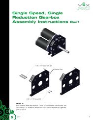
Required Supplies <strong>and</strong> SoftwareThe following supplies are used in this phase:SuppliesNotebook <strong>and</strong> penOne assembled <strong>VEX</strong> motor test st<strong>and</strong> from the Unit 5: Speed, Power, Torque, <strong>and</strong> DC Motors > Build PhaseWork surfaceSmall storage container for loose partsOptional: Autodesk Inventor Professional 2009<strong>VEX</strong> PartsThe following <strong>VEX</strong> parts are used in this phase:Quantity Part Number Abbreviations5 BEARING-FLAT BF10 NUT-832-KEPS NK10 SCREW-832-0500 S42 SHAFT-3000 SQ32 SHAFT-COLLAR COL1 SPACER-THICK SP21 SPACER-THIN SP11 <strong>VEX</strong>-12-TOOTH-GEAR G121 <strong>VEX</strong>-84-TOOTH-GEAR G842 WASHER-DELRIN WPActivity <strong>Gears</strong>ActivityIn this activity, you add a single-stage gear reduction to the test st<strong>and</strong> from Unit 5 to enable the liftingof heavier objects.As you work on building this project, have some of your team members focus on exp<strong>and</strong>ingtheir expertise using Autodesk Inventor. Later in the curriculum, you will be challenged to come upwith your own creative solutions for robot design. You will save time <strong>and</strong> maximize your ability tocreate winning solutions if your team underst<strong>and</strong>s how to leverage the power of digital prototypesusing Inventor.Build Phase■47
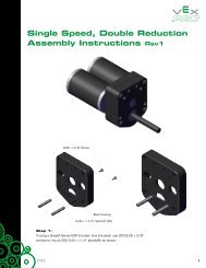
NOTE: Team members can download a free version of Autodesk Inventor Professional to use at home,so you can come to class prepared to build <strong>and</strong> test your best ideas! To do this, simply join theAutodesk Student Engineering <strong>and</strong> Design Community at http://www.autodesk.com/edcommunity.1. To complete the next step:■■Remove the 1x2x1x15 C-Channel from the existing test st<strong>and</strong>.Remove the motor from the 1x2x1x15 C-Channel.The completed model is as shown:48■Unit 6: <strong>Gears</strong>, <strong>Chains</strong>, <strong>and</strong> <strong>Sprockets</strong>
2. To complete the next step:■■Re-bolt the motor into its new position on the 1x2x1x15 C-Channel.Bolt the two Bearing Flats [BF] to the 1x2x1x15 C-Channel.The completed model is as shown:Build Phase■49
3. To complete the next step:■Bolt four Bearing Flats to the test st<strong>and</strong>.The completed model is as shown:50■Unit 6: <strong>Gears</strong>, <strong>Chains</strong>, <strong>and</strong> <strong>Sprockets</strong>
4. To complete the next step:■■■■■■■Slide the 84 Tooth Gear [G84] <strong>and</strong> a Thick Spacer [SP2] onto the 4" shaft from the test st<strong>and</strong>.Slide two Collars [COL], a 12 Tooth Gear [G12], a Thin Spacer [SP1], <strong>and</strong> 2 Delrin Washers[WP] on a 3" shaft [SQ3].Insert the 3" Shaft into the Bearing Flat.Bolt the assembly from the previous step to the 2" St<strong>and</strong>offs on the test st<strong>and</strong>.Insert the 3" Shaft fully into the Motor <strong>and</strong> tighten the two Shaft Collars.Slide the 84 Tooth Gear <strong>and</strong> Thick Spacer up against the Bearing Flat you attached tothe 1x2x1x15 C-Channel <strong>and</strong> tighten the Shaft Collars.Ensure that the 84 Tooth Gear <strong>and</strong> 12 Tooth Gear are aligned such that the teeth mesh.The completed model is as shown:Build Phase■51
5. Your test st<strong>and</strong> is now complete <strong>and</strong> ready for use.52■Unit 6: <strong>Gears</strong>, <strong>Chains</strong>, <strong>and</strong> <strong>Sprockets</strong>
Amaze PhaseOverviewIn this phase, you try <strong>and</strong> lift a 5 lb. weight as quickly as possible using the modified test st<strong>and</strong> fromthe Unit 6: <strong>Gears</strong>, <strong>Chains</strong>, <strong>and</strong> <strong>Sprockets</strong> > Build Phase.Phase ObjectivesAfter completing this phase, you will be able to:■■■Modify the gearing of a <strong>VEX</strong> gearbox.Describe the effect of gear ratios on speed <strong>and</strong> torque.Be able to determine an appropriate gear ratio to complete a mechanical task.Prerequisites <strong>and</strong> ResourcesBefore starting this phase, you must have:■■Completed the Unit 6: <strong>Gears</strong>, <strong>Chains</strong>, <strong>and</strong> <strong>Sprockets</strong> > Think Phase.Completed the Unit 6: <strong>Gears</strong>, <strong>Chains</strong>, <strong>and</strong> <strong>Sprockets</strong> > Build Phase.■Have assembled the gear ratio test st<strong>and</strong> from the Unit 6: <strong>Gears</strong>, <strong>Chains</strong>, <strong>and</strong> <strong>Sprockets</strong> >Build Phase.Related phase resources are:■■■Unit 1: Introduction to <strong>VEX</strong> <strong>and</strong> <strong>Robotics</strong>.Unit 4: Microcontroller <strong>and</strong> Transmitter Overview.Unit 5: Speed, Power, Torque, <strong>and</strong> DC Motors.Amaze Phase■53
Required Supplies <strong>and</strong> SoftwareThe following supplies are used in this phase:SuppliesAn assembled the gear ratio test st<strong>and</strong> from the Unit 6: <strong>Gears</strong>, <strong>Chains</strong>, <strong>and</strong> <strong>Sprockets</strong> > Build PhaseNotebook <strong>and</strong> pen5 lb. weightOne stopwatchA surface (for example, a table or desk) with an edge at least 24” above the ground<strong>VEX</strong> PartsThe following <strong>VEX</strong> parts are used in this phase:Quantity Part Number Abbreviations1 <strong>VEX</strong>-36-TOOTH-GEAR G361 <strong>VEX</strong>-60-TOOTH-GEAR G60EvaluationChallengeUsing the <strong>Gears</strong> Ratio Test St<strong>and</strong>, determine the gear ratio that enables you to lift the 5 lb. weight asfast as possible.Instructions1. Looking back at Unit 5: Speed, Power, Torque, <strong>and</strong> DC Motors > Think Phase, remember that youcan alter the speed of a system by changing the gear ratios. The smaller the reduction, the fasterthe output speed, but with a less amount of torque. The key to this exercise is to find the smallestreduction that still has enough torque to lift the 5 lb. mass.2. In this phase, you test five different gear ratios, 12:84, 12:60, 36:84, 36:60, 60:84. To do each of thesetests, the Gear Ration Test St<strong>and</strong> needs to be modified appropriately.3. For each gear ratio, perform the following test. For information on how to change the gear ratios,see the section below.a. Plug the motor into port 6 of your Microcontroller.b. Plug the Transmitter into port 1 of the Microcontroller.c. Plug the 7.2V battery into the Microcontroller.d. Turn both your Transmitter <strong>and</strong> Microcontroller on.e. Using the yellow buttons on the back of the Transmitter, you should be able to control therotation of the pulley.54■Unit 6: <strong>Gears</strong>, <strong>Chains</strong>, <strong>and</strong> <strong>Sprockets</strong>
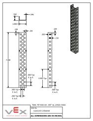
f. Set up the test st<strong>and</strong> between two tables, with the string hanging between them. Let thestring hang 24” below the surface top.g. Attach the 5 lb. mass to the string.h. Using the Transmitter, have the test st<strong>and</strong> lift the mass. Using the stopwatch, time how long ittakes for the mass to reach the surface. Record this time in your engineering notebook. If thetest st<strong>and</strong> is unable to generate enough torque to lift the mass, record it in your chart.How to Change the Gear Ratio1. Remove the 1x2x1x15 C-Channel that the motor is attached to by removing the bolts at either endof the channel.2. Remove the motor <strong>and</strong> bearing flat from the 1x2x1x15 C-Channel, <strong>and</strong> reattach it to the properholes for the new gear ratio. See figures 1-5 to determine the proper mounting location.3. Remove the spacers from both the drive <strong>and</strong> driven shafts. Place these spacers in separate piles,so they can easily be put back on the appropriate shafts.4. Remove both the drive <strong>and</strong> driven gears.5. Loosen <strong>and</strong> remove both collars on the drive shaft.6. Remove the drive shaft from the bearing flat.7. Depending on your new ratio, insert the drive shaft into its new appropriate bearing flat.See figures 1-5.8. Replace both collars on the drive shaft.9. Slide the appropriate gears onto their shafts. Make sure the gears are aligned such that they meshproperly.10. Replace the spacers on the shafts.11. Reattach the 1x2x1x15 C-Channel.12. Your test st<strong>and</strong> is now ready for operation with your new gear ratio.Figure 1: 12:84 ReductionAmaze Phase■55
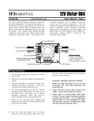
Figure 2: 12:60 ReductionFigure 3: 36:84 Reduction56■Unit 6: <strong>Gears</strong>, <strong>Chains</strong>, <strong>and</strong> <strong>Sprockets</strong>
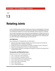
Figure 4: 36:60 ReductionFigure 5: 60:84 ReductionAmaze Phase■57
Engineering NotebookCreate the following blank chart in your engineering notebook:Drive Gear Driven Gear ReductionRatioPulley FreeSpeed (RPM)CalculatedMotorTorqueTime to lift24"12 8412 6036 8436 6060 84■■■■Using the knowledge you gained on gearing, speed, power, <strong>and</strong> torque in the previous ThinkPhases, complete your chart appropriately. Remember the following:Reduction Ratio = # teeth of drive gear / # teeth of driven gear.Free Speed = Motor Free Speed x Reduction Ratio. Go back to your notes from the Unit 5: <strong>Gears</strong>,<strong>Chains</strong>, <strong>and</strong> Sprocket > Amaze Phase, where you calculated the free speed of a <strong>VEX</strong> motor.Motor Torque = Mass x Pulley Radius x Reduction Ratio.Create a graph showing the relationship between the Reduction Ratio <strong>and</strong> Time to Lift the mass.In your notebook, discuss the shape of your graph. Does it surprise you?How can you lift the mass even faster using this test st<strong>and</strong>? How would it need to be modified?Discuss what changes you would make to accomplish this task. If time remains, execute your plan.PresentationPrepare your findings from this phase, <strong>and</strong> present them to the class. Explain why you <strong>and</strong> yourclassmates may not all have the same results. Discuss how you can modify the test st<strong>and</strong> to lift theweight even faster.58■Unit 6: <strong>Gears</strong>, <strong>Chains</strong>, <strong>and</strong> <strong>Sprockets</strong>
STEM ConnectionsBackgroundThe United States Coast Guard often uses rescue helicopters when responding to maritimeemergencies. These helicopters can assist in rescue efforts by hovering above their target <strong>and</strong>inserting a rescue swimmer whose job it is to reach the survivor <strong>and</strong> stay with them until bothswimmers can be extracted via a rescue line from the helicopter. The helicopter extraction isaccomplished with a winch system similar to the <strong>VEX</strong> Test St<strong>and</strong> you use for this unit.ScienceCoast Guard rescue helicopters often operate in extreme conditions. As a result, the winch systemsinvolved in ocean rescue must be able to withst<strong>and</strong> the harsh ocean environment.1. What are some of the material science transformation processes (for example, corrosion) that youneed to consider when designing a winch for this sort of application?2. What associated problems can occur if the winch system is not designed to resist these harshconditions?3. What materials can you use to build a weather resistant winch system, <strong>and</strong> how do those materialsaffect the operation of the winch?4. Design a laboratory test to determine which materials are the best choice for these conditions.TechnologyConsider that the helicopter’s winch system may be subject to very different loads, given differentrescue circumstances. For instance, the weight of the survivors, the number of survivors, <strong>and</strong> theweather <strong>and</strong> water conditions can all affect the load.1. How would a system that switches gear ratios based on the potential load improve the efficiencyof the rescue winch system?2. How can this be accomplished?STEM Connections■59
Engineering1. If you were designing the winch system for a Coast Guard search <strong>and</strong> rescue helicopter, howwould you adjust the mechanism’s speed <strong>and</strong> torque with gear ratios to maximize the efficiency<strong>and</strong> utility of the system?2. How would you test the system to reach your goal of maximum efficiency?MathSuppose a rescue helicopter is lifting a swimmer out of the water. The total load at the end of the cableis 210 lbs. The winch works by turning an axle, about which the cable becomes spooled.1. What is the torque when the spool has a radius of 3 inches?2. As more cable is drawn in <strong>and</strong> the spool grows, the radius becomes 5 inches. What is thenew torque?60■Unit 6: <strong>Gears</strong>, <strong>Chains</strong>, <strong>and</strong> <strong>Sprockets</strong>