

LTC2410 24-Bit No Latency âΣTM ADC with Differential Input and ...
LTC2410 24-Bit No Latency âΣTM ADC with Differential Input and ...
LTC2410 24-Bit No Latency âΣTM ADC with Differential Input and ...

Create successful ePaper yourself
Turn your PDF publications into a flip-book with our unique Google optimized e-Paper software.
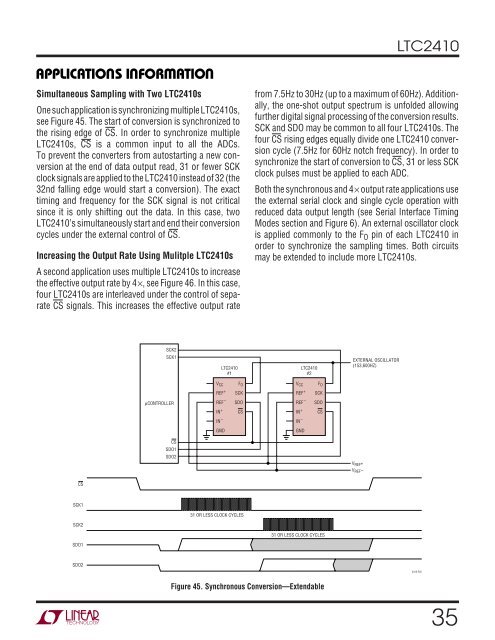
<strong>LTC<strong>24</strong>10</strong>APPLICATIO S I FORATIOU W U USimultaneous Sampling <strong>with</strong> Two <strong>LTC<strong>24</strong>10</strong>sOne such application is synchronizing multiple <strong>LTC<strong>24</strong>10</strong>s,see Figure 45. The start of conversion is synchronized tothe rising edge of CS. In order to synchronize multiple<strong>LTC<strong>24</strong>10</strong>s, CS is a common input to all the <strong>ADC</strong>s.To prevent the converters from autostarting a new conversionat the end of data output read, 31 or fewer SCKclock signals are applied to the <strong>LTC<strong>24</strong>10</strong> instead of 32 (the32nd falling edge would start a conversion). The exacttiming <strong>and</strong> frequency for the SCK signal is not criticalsince it is only shifting out the data. In this case, two<strong>LTC<strong>24</strong>10</strong>’s simultaneously start <strong>and</strong> end their conversioncycles under the external control of CS.Increasing the Output Rate Using Mulitple <strong>LTC<strong>24</strong>10</strong>sA second application uses multiple <strong>LTC<strong>24</strong>10</strong>s to increasethe effective output rate by 4×, see Figure 46. In this case,four <strong>LTC<strong>24</strong>10</strong>s are interleaved under the control of separateCS signals. This increases the effective output ratefrom 7.5Hz to 30Hz (up to a maximum of 60Hz). Additionally,the one-shot output spectrum is unfolded allowingfurther digital signal processing of the conversion results.SCK <strong>and</strong> SDO may be common to all four <strong>LTC<strong>24</strong>10</strong>s. Thefour CS rising edges equally divide one <strong>LTC<strong>24</strong>10</strong> conversioncycle (7.5Hz for 60Hz notch frequency). In order tosynchronize the start of conversion to CS, 31 or less SCKclock pulses must be applied to each <strong>ADC</strong>.Both the synchronous <strong>and</strong> 4× output rate applications usethe external serial clock <strong>and</strong> single cycle operation <strong>with</strong>reduced data output length (see Serial Interface TimingModes section <strong>and</strong> Figure 6). An external oscillator clockis applied commonly to the F O pin of each <strong>LTC<strong>24</strong>10</strong> inorder to synchronize the sampling times. Both circuitsmay be extended to include more <strong>LTC<strong>24</strong>10</strong>s.SCK2SCK1<strong>LTC<strong>24</strong>10</strong>#1<strong>LTC<strong>24</strong>10</strong>#2EXTERNAL OSCILLATOR(153,600HZ)V CCF OV CCF OREF +SCKREF +SCKµCONTROLLERREF –IN +SDOCSREF –IN +SDOCSIN –IN –GNDGNDCSSDO1SDO2V REF +V REF –CSSCK131 OR LESS CLOCK CYCLESSCK231 OR LESS CLOCK CYCLESSDO1SDO2<strong>24</strong>10 F45Figure 45. Synchronous Conversion—Extendable35


