ARP2600 - Fundamentals of Music Technology - Cyborgstudio.com
ARP2600 - Fundamentals of Music Technology - Cyborgstudio.com
ARP2600 - Fundamentals of Music Technology - Cyborgstudio.com

Create successful ePaper yourself
Turn your PDF publications into a flip-book with our unique Google optimized e-Paper software.
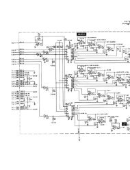
114 - SECTION FOURTEEN: PATCH DIAGRAMMING AND ANALYSISFinally, the lag processor’s level has been set. However, nothing is patched into it, and the only thingnormalled to it (the envelope follower) is doing nothing at all since its level is set <strong>com</strong>pletely down.Thus, this is another dead end.SUMMING UP PATCH ONESo, when asked to sum up this first patch, one could say that when a key is played, one will hear a slowresonant filter sweep which will eventually settle down to a moderate level. This patch’s timbre is asquare wave, and frequency modulation is occurring. The frequency <strong>of</strong> each <strong>of</strong> the two square waveswill ramp upwards then drop back to normal pitch in alteration, first VCO-2, then VCO-3. This switchingwill occur about once or twice per second. When the key is released, the filter will slowly closeuntil the patch is silent. This patch will sound mostly from the right speaker, and also has a smallamount <strong>of</strong> reverberation on it. This patch can be heard in CD track 81.If any <strong>of</strong> the conclusions drawn during the analysis <strong>of</strong> this patch were unclear, take a moment now toreturn to the pertinent section to quickly review it before moving on to the second patch.PATCH TWO: S/H WITH A TWISTWhile the second patch (see Figure 14-4 on page 115) is significantly more <strong>com</strong>plex than the first, it isstill easy to predict how it will sound. Once again, one must begin by trying to determine what will beproducing the sound. In this particular patch, the VCF slider is raised in the mixer, but something hasbeen patched to it. Jack C <strong>of</strong> the electronic switch has been connected, which would indicate that jackC is functioning as an output. When jack C is an output, the electronic switch is being used to create aswitching patch.Following the signal path backwards, one can see that there is a patch cord connected to jack A <strong>of</strong> theelectronic switch, but nothing is connected to jack B. Thus, the electronic switch will be switchingbetween the sound <strong>com</strong>ing in jack A and silence. The VCA’s output is connected to jack A. The VCA’sgain is set fully closed which means that no sound can <strong>com</strong>e through for the time being, but since one<strong>of</strong> the control inputs has something connected to it and the appropriate slider is raised, it is still possiblethat sound could be produced.One <strong>of</strong> the VCA’s two audio inputs has its slider raised, allowing the output <strong>of</strong> the filter to flow in. Likethe VCA, the filter’s Fc is <strong>com</strong>pletely closed. Once again, something is connected to one <strong>of</strong> the controlinputs (actually both on the filter), so a provision has been made for the Fc to be raised, thereby lettingsound through.The VCF is being fed by a host <strong>of</strong> sources. All three oscillators are connected, all using their sawtoothoutputs. Their levels are all raised in the filter, and they all seem to be tuned in unison since the INI-TIAL FREQUENCY sliders are all roughly in the same place. In addition to the VCOs, the ring modulatorand the noise generator are also present, although the noise generator’s volume is being attenuateda bit.