2 - Big Ass Fans
2 - Big Ass Fans
2 - Big Ass Fans

Create successful ePaper yourself
Turn your PDF publications into a flip-book with our unique Google optimized e-Paper software.
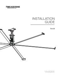
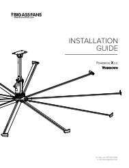
Fan diagram8’–24’ POWERFOIL ® X2.0 & 10’–24’ POWERFOIL ® X2.0PLUS FANSPre-Installation (cont.)7A. Safety Cable. A redundant safety feature that secures the fan to themounting structure.B. Upper Yoke. Secures the fan to the mounting structure and allows the fanto adjust its center of gravity.C. Extension Tube. Extends the fan from the ceiling.D. Lower Yoke. Connects the main fan assembly to the extension tube.E. VFD Enclosure. Contains the variable-frequency drive.F. Gearbox. NitroSeal Drive custom gearbox for increased durability andcooler operation.G. Motor. See pages 2–3 for more information.H. Hub. Secures the airfoils to the gearbox output shaft.I. Airfoil. Provides air movement. The unique, patented design providesJ. AirFence. Improves the performance of the fan.K. Winglet (Powerfoil ® [shown] or Powerfoil ® Plus). and performance of the fan.BACDEGFHIJKWWW.BIGASSFANS.COM ©2012 DELTA T CORP. DBA BIG ASS FAN CO. ALL RIGHTS RESERVED