

EO18-12003 - toshiba tec europe
EO18-12003 - toshiba tec europe
EO18-12003 - toshiba tec europe
- No tags were found...

You also want an ePaper? Increase the reach of your titles
YUMPU automatically turns print PDFs into web optimized ePapers that Google loves.
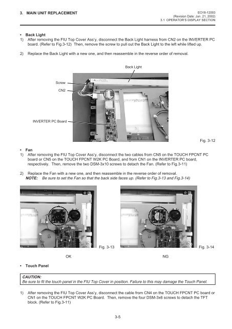
3. MAIN UNIT REPLACEMENT <strong>EO18</strong>-<strong>12003</strong>(Revision Date: Jun. 21, 2002)3.1 OPERATOR’S DISPLAY SECTION• Back Light1) After removing the FIU Top Cover Ass’y, disconnect the Back Light harness from CN2 on the INVERTER PCboard. (Refer to Fig.3-12) Then, remove the screw to pull out the Back Light to the left while lifted up.2) Replace the Back Light with a new one, and then reassemble in the reverse order of removal.Back LightScrewCN2INVERTER PC Board• Fan1) After removing the FIU Top Cover Ass’y, disconnect the two cables from CN5 on the TOUCH FPCNT PCboard or CN5 on the TOUCH FPCNT W2K PC Board, and from CN1 on the INVERTER PC board,respectively. Then, remove the two DSM-3x10 screws to detach the Fan. (Refer to Fig.3-11)2) Replace the Fan with a new one, and then reassemble in the reverse order of removal.NOTE: Be sure to set the Fan so that the back side faces up. (Refer to Fig.3-13 and Fig.3-14)Fig. 3-12Fig. 3-13 Fig. 3-14OKNG• Touch PanelCAUTION:Be sure to fit the touch panel in the FIU Top Cover in position. Failure to this may damage the Touch Panel.1) After removing the FIU Top Cover Ass’y, disconnect the cable from CN4 on the TOUCH FPCNT PC board orCN1 on the TOUCH FPCNT W2K PC Board. Then, remove the four DSM-3x6 screws to detach the TFTblock. (Refer to Fig.3-11)3-5


