

EO18-12003 - toshiba tec europe
EO18-12003 - toshiba tec europe
EO18-12003 - toshiba tec europe
- No tags were found...

You also want an ePaper? Increase the reach of your titles
YUMPU automatically turns print PDFs into web optimized ePapers that Google loves.
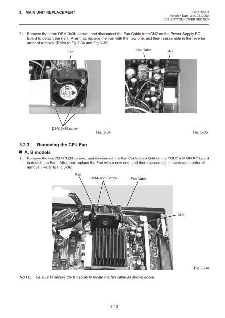
3. MAIN UNIT REPLACEMENT <strong>EO18</strong>-<strong>12003</strong>(Revision Date: Jun. 21, 2002)3.2 BOTTOM COVER SECTION2) Remove the three DSM-3x35 screws, and disconnect the Fan Cable from CN2 on the Power Supply PCBoard to detach the Fan. After that, replace the Fan with the new one, and then reassemble in the reverseorder of removal (Refer to Fig.3-34 and Fig.3-35).FanFan CableCN2DSM-3x35 screwFig. 3-34 Fig. 3-353.2.3 Removing the CPU FanA, B models1) Remove the two DSM-3x25 screws, and disconnect the Fan Cable from CN4 on the TOUCH MAIN PC boardto detach the Fan. After that, replace the Fan with a new one, and then reassemble in the reverse order ofremoval (Refer to Fig.3-36).FanDSM-3x25 ScrewFan CableCN4Fig. 3-36NOTE:Be sure to secure the fan so as to locate the fan cable as shown above.3-13


