

EO18-12003 - toshiba tec europe
EO18-12003 - toshiba tec europe
EO18-12003 - toshiba tec europe
- No tags were found...

Create successful ePaper yourself
Turn your PDF publications into a flip-book with our unique Google optimized e-Paper software.
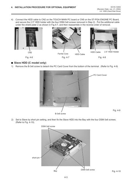
4. INSTALLATION PROCEDURE FOR OPTIONAL EQUIPMENT <strong>EO18</strong>-<strong>12003</strong>(Revision Date: Jun. 21, 2002)4.4 HDD (Hard Disk Drive)4) Connect the HDD cable to CN2 on the TOUCH MAIN PC board or CN5 on the ST-PGA ENGINE PC Board,and secure the 2.5" HDD holder with the four DSM-3x6 screws removed in Step 2). Put the additional cableunder the shield plate U as shown in Fig.4-7, and then reassemble in the reverse order of removal.CN2HDD Cable 2.5” HDD HolderFerrite Core HDD CableFig. 4-6 Fig. 4-7 Fig. 4-8Slave HDD (C model only)1) Remove the B-3x6 screw to detach the PC Card Cover from the bottom of the terminal. (Refer to Fig. 4-9)PC Card CoverB-3x6 screwFig. 4-92) Set to Slave by short pin setting, and then fix the Slave HDD into the Bay with the four DSM-3x6 screws.(Refer to Fig. 4-10).DSM-3x6 screwshort pinBayDSM-3x6 screwFig. 4-104-3


