

EO18-12003 - toshiba tec europe
EO18-12003 - toshiba tec europe
EO18-12003 - toshiba tec europe
- No tags were found...

You also want an ePaper? Increase the reach of your titles
YUMPU automatically turns print PDFs into web optimized ePapers that Google loves.
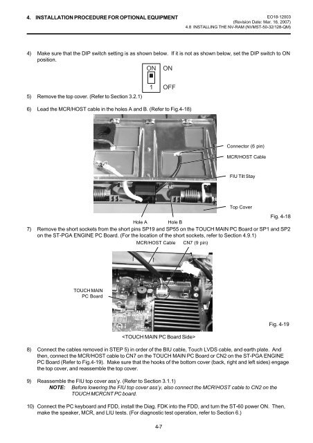
4. INSTALLATION PROCEDURE FOR OPTIONAL EQUIPMENT <strong>EO18</strong>-<strong>12003</strong>(Revision Date: Mar. 16, 2007)4.8 INSTALLING THE NV-RAM (NVMST-50-32/128-QM)4) Make sure that the DIP switch setting is as shown below. If it is not as shown below, set the DIP switch to ONposition.ON ON5) Remove the top cover. (Refer to Section 3.2.1)1OFF6) Lead the MCR/HOST cable in the holes A and B. (Refer to Fig.4-18)Connector (6 pin)MCR/HOST CableFIU Tilt StayTop CoverFig. 4-18Hole A Hole B7) Remove the short sockets from the short pins SP19 and SP55 on the TOUCH MAIN PC Board or SP1 and SP2on the ST-PGA ENGINE PC Board. (For the location of the short sockets, refer to Section 4.9.1)MCR/HOST CableCN7 (9 pin)TOUCH MAINPC Board4-7Fig. 4-198) Connect the cables removed in STEP 5) in order of the BIU cable, Touch LVDS cable, and earth plate. Andthen, connect the MCR/HOST cable to CN7 on the TOUCH MAIN PC Board or CN2 on the ST-PGA ENGINEPC Board (Refer to Fig.4-19). Make sure that the hooks of the bottom cover (back, right and left sides) engagethe top cover, and reassemble the top cover.9) Reassemble the FIU top cover ass’y. (Refer to Section 3.1.1)NOTE: Before lowering the FIU top cover ass’y, also connect the MCR/HOST cable to CN2 on theTOUCH MCRCNT PC board.10) Connect the PC keyboard and FDD, install the Diag. FDK into the FDD, and turn the ST-60 power ON. Then,make the speaker, MCR, and LIU tests. (For diagnostic test operation, refer to Section 6.)


