

EO18-12003 - toshiba tec europe
EO18-12003 - toshiba tec europe
EO18-12003 - toshiba tec europe
- No tags were found...

Create successful ePaper yourself
Turn your PDF publications into a flip-book with our unique Google optimized e-Paper software.
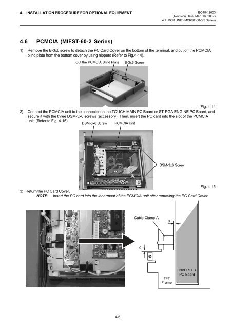
4. INSTALLATION PROCEDURE FOR OPTIONAL EQUIPMENT <strong>EO18</strong>-<strong>12003</strong>(Revision Date: Mar. 16, 2007)4.7 MCR UNIT (MCRST-60-3/5 Series)4.6 PCMCIA (MIFST-60-2 Series)1) Remove the B-3x6 screw to detach the PC Card Cover on the bottom of the terminal, and cut off the PCMCIAblind plate from the bottom cover by using nippers (Refer to Fig.4-14).Cut the PCMCIA Blind Plate B-3x6 ScrewFig. 4-142) Connect the PCMCIA unit to the connector on the TOUCH MAIN PC Board or ST-PGA ENGINE PC Board, andsecure it with the three DSM-3x6 screws (accessory). Then, insert the PC card into the slot of the PCMCIAunit. (Refer to Fig. 4-15)DSM-3x6 Screw PCMCIA UnitDSM-3x6 ScrewFig. 4-153) Return the PC Card Cover.NOTE: Insert the PC card into the innermost of the PCMCIA unit after removing the PC Card Cover.Cable Clamp A00TFTFrameINVERTERPC Board4-5


