Applied Superconductivity - Walther Meißner Institut - Bayerische ...
Applied Superconductivity - Walther Meißner Institut - Bayerische ...
Applied Superconductivity - Walther Meißner Institut - Bayerische ...
- No tags were found...

Create successful ePaper yourself
Turn your PDF publications into a flip-book with our unique Google optimized e-Paper software.
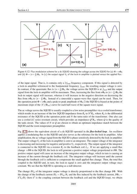
Section 4.1 APPLIED SUPERCONDUCTIVITY 177VVΦ(c)ΦΦ = n Φ 0V LΦΦ = (n+ 1/4) Φ 0(a)(n+1/2) Φ 0(b)Figure 4.12: Flux modulation scheme for a dc-SQUID showing the voltage across the SQUID for (a) Φ = nΦ 0and (b) Φ = (n + 1 4 )Φ 0. In (c) the output signal V L of the lock-in amplifier is plotted versus the applied flux.of the input signal. That is, it contains only a 2 f mod frequency component. If this signal is detected bya lock-in amplifier referenced to the fundamental frequency f mod , the resulting output voltage is zero.In contrast, if the quasistatic flux is (n + 1 4 )Φ 0, the voltage across the SQUID is at f mod and the outputsignal from the lock-in amplifier will be maximum. Thus, increasing the flux from nΦ 0 to (n + 1 4 )Φ 0 thelock-in output signal will increase, whereas it will increase in the negative direction on decreasing theflux from nΦ 0 to (n − 1 4 )Φ 0. Instead of a sinusoidal a square-wave flux signal can be used. Then, forthe operation point Φ = nΦ 0 and a peak-to-peak amplitude of Φ 0 /2 the SQUID is biased at the points ofmaximum slope of the 〈V 〉(Φ ext ) curve for each half-wave of the square-wave signal.The ac voltage across the SQUID is usually coupled to a low noise preamplifier via a cooled transformer,which results in an increase of the low SQUID impedance from R d to N 2 R d , where R d is the differentialresistance of the SQUID at the operation point and N the turns-ratio of the transformer. One also canuse a cooled LC series resonant circuit, which provides an impedance Q 2 R d , where Q is the quality ofthe tank circuit. The values of N or Q are chosen to obtain an optimum impedance match between theSQUID and the room temperature preamplifier.Fig. 4.13 shows the equivalent circuit of a dc-SQUID operated in the flux-locked loop. An oscillatorapplies a modulating flux to the SQUID and also serves as the reference for the lock-in amplifier. Afteramplification, the ac voltage signal from the SQUID is phase sensitively detected by the lock-in amplifier.The output voltage V L of the lock-in amplifier is sent to an integrator. The output voltage of the integratoris decreasing and increasing for negative and positive V L , respectively. The output signal of the integratoris connected to the SQUID via a resistor R f to the feedback coil L f . If we are applying a small fluxchange +δΦ to the SQUID, the lock-in will generate a positive output voltage proportional to δΦ. Thepositive output signal will cause an increase of the integrator output voltage, which in turn is causing anincrease of the current through the feedback coil. The integrator voltage will increase until the currentthrough the feedback coil is sufficient to compensate the small applied flux change. Then, the total fluxcoupled to the SQUID and, in turn, the lock-in signal is zero and the integrator output voltage staysconstant. We see that the SQUID is operating as a null detector.The change δV in of the integrator output voltage is directly proportional to the flux change δΦ. Withthe change of the feedback current δI f = δV in /R f and the flux induced by the feedback current, δΦ f =k 2 L f δI f (here k 2 is the coupling constant between the feedback coil and the SQUID loop), we obtain2005