Applied Superconductivity - Walther Meißner Institut - Bayerische ...
Applied Superconductivity - Walther Meißner Institut - Bayerische ...
Applied Superconductivity - Walther Meißner Institut - Bayerische ...
- No tags were found...

You also want an ePaper? Increase the reach of your titles
YUMPU automatically turns print PDFs into web optimized ePapers that Google loves.
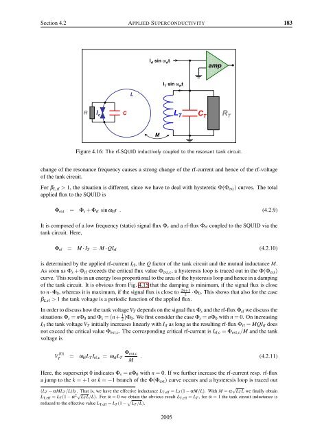
Section 4.2 APPLIED SUPERCONDUCTIVITY 183I rfsin ω rftI Tsin ω rftLR I c CL TC TampR TMFigure 4.16: The rf-SQUID inductively coupled to the resonant tank circuit.change of the resonance frequency causes a strong change of the rf-current and hence of the rf-voltageof the tank circuit.For β L,rf > 1, the situation is different, since we have to deal with hysteretic Φ(Φ ext ) curves. The totalapplied flux to the SQUID isΦ ext = Φ s + Φ rf sinω rf t . (4.2.9)It is composed of a low frequency (static) signal flux Φ s and a rf-flux Φ rf coupled to the SQUID via thetank circuit. Here,Φ rf = M · I T = M · QI rf (4.2.10)is determined by the applied rf-current I rf , the Q factor of the tank circuit and the mutual inductance M.As soon as Φ s + Φ rf exceeds the critical flux value Φ ext,c , a hysteresis loop is traced out in the Φ(Φ ext )curve. This results in an energy loss proportional to the area of the hysteresis loop and hence in a dampingof the tank circuit. It is obvious from Fig. 4.15 that the damping is minimum, if the signal flux is closeto n · Φ 0 , whereas it is maximum, if the signal flux is close to 2n+12· Φ 0 . This shows that also for the caseβ L,rf > 1 the tank voltage is a periodic function of the applied flux.In order to discuss how the tank voltage V T depends on the signal flux Φ s and the rf-flux Φ rf we discuss thesituations Φ s = nΦ 0 and Φ s = (n+ 1 2 )Φ 0. We first consider the case Φ s = nΦ 0 with n = 0. On increasingI rf the tank voltage V T initially increases linearly with I rf as long as the resulting rf-flux Φ rf = MQI rf doesnot exceed the critical value Φ ext,c . The corresponding critical rf-current is I rf,c = Φ ext,c /M and the tankvoltage isV (0)T = ω rf L T I rf,c = ω rf L TΦ ext,cM . (4.2.11)Here, the superscript 0 indicates Φ s = nΦ 0 with n = 0. If we further increase the rf-current resp. rf-fluxa jump to the k = +1 or k = −1 branch of the Φ(Φ ext ) curve occurs and a hysteresis loop is traced out(L T − αML T /L)I T . That is, we have the effective inductance L T,eff = L T (1 − αM/L). With M = α √ L T L we finally obtainL T,eff = L T (1 − α 2√ L T L/L). For α = 0 we obtain the obvious result L T,eff = L T , for α = 1 the tank circuit inductance isreduced to the effective value L T,eff = L T (1 − √ L T /L).2005