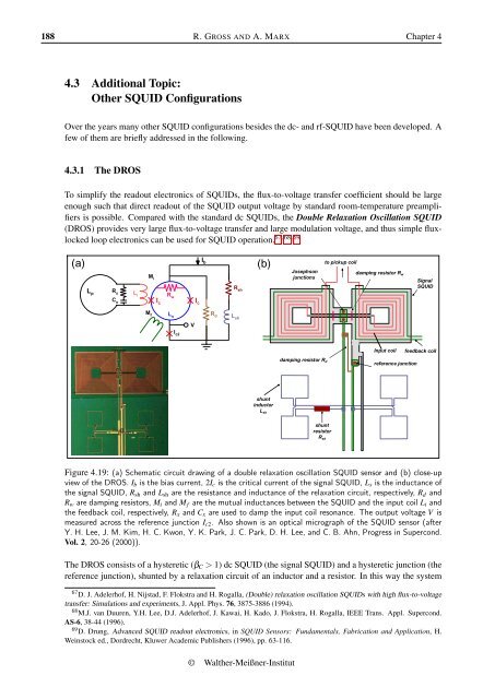
188 R. GROSS AND A. MARX Chapter 44.3 Additional Topic:Other SQUID ConfigurationsOver the years many other SQUID configurations besides the dc- and rf-SQUID have been developed. Afew of them are briefly addressed in the following.4.3.1 The DROSTo simplify the readout electronics of SQUIDs, the flux-to-voltage transfer coefficient should be largeenough such that direct readout of the SQUID output voltage by standard room-temperature preamplifiersis possible. Compared with the standard dc SQUIDs, the Double Relaxation Oscillation SQUID(DROS) provides very large flux-to-voltage transfer and large modulation voltage, and thus simple fluxlockedloop electronics can be used for SQUID operation. 67,68,69(a)L pR xC xL iM iM fI cR wL sI c2VI cI bR dR shL sh(b)to pickup coilJosephsondamping resistor R wjunctionsSignalSQUIDInput coil feedback coildamping resistor R dreference junctionshuntinductorL shshuntresistorR shFigure 4.19: (a) Schematic circuit drawing of a double relaxation oscillation SQUID sensor and (b) close-upview of the DROS. I b is the bias current, 2I c is the critical current of the signal SQUID, L s is the inductance ofthe signal SQUID, R sh and L sh are the resistance and inductance of the relaxation circuit, respectively, R d andR w are damping resistors, M i and M f are the mutual inductances between the SQUID and the input coil L i andthe feedback coil, respectively, R x and C x are used to damp the input coil resonance. The output voltage V ismeasured across the reference junction I c2 . Also shown is an optical micrograph of the SQUID sensor (afterY. H. Lee, J. M. Kim, H. C. Kwon, Y. K. Park, J. C. Park, D. H. Lee, and C. B. Ahn, Progress in Supercond.Vol. 2, 20-26 (2000)).The DROS consists of a hysteretic (β C > 1) dc SQUID (the signal SQUID) and a hysteretic junction (thereference junction), shunted by a relaxation circuit of an inductor and a resistor. In this way the system67 D. J. Adelerhof, H. Nijstad, F. Flokstra and H. Rogalla, (Double) relaxation oscillation SQUIDs with high flux-to-voltagetransfer: Simulations and experiments, J. Appl. Phys. 76, 3875-3886 (1994).68 M.J. van Duuren, Y.H. Lee, D.J. Adelerhof, J. Kawai, H. Kado, J. Flokstra, H. Rogalla, IEEE Trans. Appl. Supercond.AS-6, 38-44 (1996).69 D. Drung, Advanced SQUID readout electronics, in SQUID Sensors: Fundamentals, Fabrication and Application, H.Weinstock ed., Dordrecht, Kluwer Academic Publishers (1996), pp. 63-116.© <strong>Walther</strong>-Meißner-<strong>Institut</strong>
Section 4.3 APPLIED SUPERCONDUCTIVITY 189performs relaxation oscillations (cf. section 4.1.5). Instead of the reference junction also a referenceSQUID can be used. However, the reference junction has the advantage to be less susceptible for fluxtrapping than the reference SQUID and to eliminate the lines needed for the adjustment of a referenceflux.The schematic circuit drawing of the DROS planar gradiometer and the close-up view of the DROSare shown in Fig. 4.19a and b, respectively. In an adequate bias current range, the DROS functions asa comparator of the two critical currents, namely the signal critical current and the reference criticalcurrent. Thus, the voltage output of the DROS behaves like a square-wave function as the signal fluxchanges, resulting in a very large flux-to-voltage transfer coefficient when the two critical currents areequal.As an example, in Fig. 4.19b a gradiometer-type signal SQUID is shown with two square-shaped washersconnected in parallel. A reference junction is used instead of the reference SQUID. The high flux-tovoltagetransfer coefficient of typically 3 mV/Φ 0 enables direct readout by simple room temperatureelectronics with a modest voltage noise. By integrating a pickup coil consisting of two planar coils(typical size: 10 × 10 mm 2 , baseline length: a few cm) connected in series on the same chip a planargradiometer with a field gradient noise of a few fT/cm Hz in the white noise regime can be obtained.4.3.2 The SQIFFor the realization of SQUIDs also interferometer structures consisting of more than two junctions canbe used. As we have seen, for β L ≪ 1 the dependence of the maximum Josephson current of a dc SQUIDon the external flux corresponds to the diffraction pattern of a double slit configuration. In analogyto optics it is evident that we can achieve an even steeper I m s (Φ ext ) dependence by using a structurecorresponding to an optical grid. Such a structure is obtained by putting N junctions in parallel. Theproblem in the realization of such structures is the requirement to fabricate a large number of identicalJosephson junctions and loops separating them. If the junction and loop parameters vary considerably,the resulting interference pattern is very irregular and hardly useful. However, recently it was pointed outthat also irregular configurations are useful. Such arrays have been named Superconducting QuantumInterference Filters (SQIFs).By using an irregular parallel array of Josephson junctions as shown in Fig. 4.20a, the resulting interferencepattern, i.e. the I m s (Φ ext ) dependence of the array shows a sharp peak at zero flux followed by a verysteep decrease. A similar result is obtained for the array voltage V (Φ ext ) at constant bias current (seeFig. 4.20b). The idea then is to use the peak in the maximum Josephson current to realize a sensitive fluxsensor. Typically, a SQIF device consists of a parallel array of several 10 Josephson junctions. Deviceswith both low-T c and high-T c Josephson junctions have been realized. 70,71 Compared to dc SQUIDs theSQIF shows a considerably higher flux-to-voltage transfer coefficient. Beyond irregular parallel arraysalso series configurations of dc SQUIDs with varying loop size and two-dimensional structures havebeen studied. 724.3.3 Cartwheel SQUIDIn so-called cartwheel SQUIDs the SQUID loop consists of several loops forming a cartwheel. The loopsare parallel to each other thereby reducing the total inductance of the SQUID loop. Cartwheel SQUIDs70 J. Oppenländer, Ch. Häussler, T. Träuble, N. Schopohl, Physica C 368, 119 (2002).71 V. Schultze, R.I. Ijsselstein, H.-G. Meyer, J. Oppenländer, Ch. Häussler, N. Schopohl, IEEE Trans. Appl. Supercond.AS-13, 775 (2003).72 J. Oppenländer, P. Caputo, Ch. Häussler, T. Träuble, J. Tomes, A. Friesch, N. Schopohl, Appl. Phys. Lett. 83, 969 (2003);IEEE Trans. Appl. Supercond. AS-13, 771 (2003).2005