KEMA - Weidmüller Interface GmbH & Co. KG
KEMA - Weidmüller Interface GmbH & Co. KG
KEMA - Weidmüller Interface GmbH & Co. KG

Create successful ePaper yourself
Turn your PDF publications into a flip-book with our unique Google optimized e-Paper software.
<strong>KEMA</strong>~<br />
REGISTERED QUALITY<br />
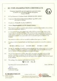
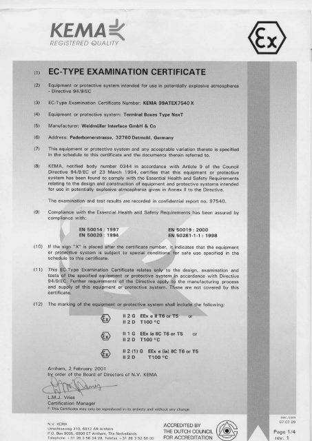
(1) EC-TYPE EXAMINATION CERTIFICATE<br />
(2) Equipment or protective system ;ntended for usa in potentially explosive atmospheres<br />
- Directive 94/9/EC<br />
(3) EC-Type Examination Certificate Number: <strong>KEMA</strong> 99ATEX7540X<br />
(4) Equipment or protective system: Terminal Baxes Type NexT<br />
(5) Manufacturer: <strong>Weidmüller</strong> <strong>Interface</strong> <strong>GmbH</strong> & <strong>Co</strong><br />
(6) Address: Paderbomerstrasse, 32760 Detmold, Germany<br />
(7) This equipment or protective system and any acceptable variation thereto is specified<br />
in the schedule to this certificate and the documents therain referred to.<br />
(BI <strong>KEMA</strong>, notified body number 0344 in accordance with Article 9 of the <strong>Co</strong>uncil<br />
Directive 94/9/EC of 23 March 1994, certifies that this equipment or protective<br />
system has been found to comply with the Essential Health and Safety Requirements<br />
relating to the design and construction of equipment and protective systems intended<br />
for use in potentially explosive atmospheres given in Annex 11to the Directive.<br />
The examination and test results are recorded in confidential report no. 97540.<br />
(9) <strong>Co</strong>mpliance with the Essential Health and Safety Requirements has been assured by<br />
compliance with:<br />
(10)<br />
(11)<br />
(12)<br />
EN 50014: 1997<br />
EN 50020 : 1994<br />
EN 50019: 2000<br />
EN 50281-1-1: 1998<br />
:r t~;O;:~i:: "~~::eI~C~~ :~~~::~et:es:i:~i:~e c~~~~~~>i~rd~:ft:sU~:a:~:;if::i~;;~~~<br />
schedule to thls certificate.<br />
;eh~;s\~~:::P~:~f:i~a~~ou~~:~~fi~~t~r~;~:~~:e °f~:~~ the a~;:~~~'~c:x:~~ag~:C;i:~<br />
94/9/ECi, Further . requir~ments of the Di~ective apPIY~ the manufacturing proce~s<br />
and supply<br />
certificate.<br />
of thls eqUipment or protectlve system. These are not covered by thls<br />
The marking of the equipll1~nt or protectivELsystem shall include the following:<br />
l.M.J. Vries<br />
Certification Manager<br />
&<br />
&<br />
&<br />
1126 EExellT6orT5 0'-<br />
1120 T100°C<br />
1I1G EExiallCT6orT5<br />
112 0 T100°C<br />
112 (1) G EEx e [ja] IIC T6 or T5<br />
1120 noo °C<br />
<strong>KEMA</strong><br />
"ThisCertificatemayonlybereproducedinitsenli,etyandwithou1 any change<br />
N.V. <strong>KEMA</strong><br />
Utrechlseweg 310, 6812 AR Arnhem<br />
P.O. Box 9035, 6800 ET Arnhem, The Nelherlands<br />
Telephooe+31263563428,Telefax+31263525800<br />
ACCREDITED BY ~<br />
THE DUTCH COUNC{L r/@--'7<br />
FüR ACCREDITATlüN -....-../
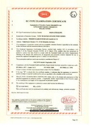
(131 S eHE 0 U l E<br />
1141 to EC-Type Examination Certificate <strong>KEMA</strong> 99ATEX7540 X<br />
(15) Description<br />
<strong>KEMA</strong>~<br />
Terminal Saxes Type NXT, made of stainless steel er painted steel. for fixed installation,<br />
provided with terminals in type of protection increased safety "e", for non-intrinsically safe<br />
aod/or intrinsically safe circuits.<br />
The area intended tor the terminals of intrinsically safe circuits is marked, e.g. in blue<br />
colour.<br />
Electrical dat8<br />
Rated voltage . .................. max. 1100 V<br />
Rated current ....<br />
Number of conductors .....<br />
<strong>Co</strong>nductor cross section<br />
Installation instructions<br />
..•.•. 1<br />
..••.. ) as per Appendix Nos. 1 up to 34<br />
...•.. 1<br />
The degree of ingress protection 01 at least IP 54 according to EN 60529 for use in<br />
potentially explosive atmospheres of f1ammable gases, vapours and mists is only achieved<br />
if certified cable entries are used that are suitable for the application and correctly<br />
installed.<br />
The degree of ingress protection of at least IP 64 according to EN 60529 for use in the<br />
presence of combustible dusts is only achieved if E· or A TEX-generation certified cable<br />
entries are used that are suitable for this application and correctly installed.<br />
At ambient temperatures exceeding + 40 oe, suitable heat resisting cables and cable<br />
glands shall be used with an operating temperature of at least 85 oe.<br />
For external earthing and bonding connection a cable lug shall be used so that the<br />
conductor is secured against loosening and twisting and that the contact pressure is<br />
permanently secured.<br />
Routine test<br />
If factory wired, each terminal box shall be submitted to a dielectric strength test<br />
according to Glause 7.1 of EN 50019.<br />
(16) Report<br />
<strong>KEMA</strong> No. 97540<br />
Page 2/4
SCHEDUlE<br />
{141 to EC-Type Examination Certificate <strong>KEMA</strong> 99ATEX7540 X<br />
1171 Special conditions for safe usa<br />
<strong>KEMA</strong>~<br />
When the Terminal Saxes are used in potentially explosive atmospheres of flammable<br />
gases, vapours or mists, the following information is to be taken into account.<br />
The marking includes: ~ 112G EExellT6orT5 or<br />
~ 111 G EExiallCT6orT5 or<br />
G 112 (1) G EEx e (ja] IIC T6 or T5<br />
The relation batwaen the gasket material, the ambient temperature range and the<br />
temperature class is given in the table below:<br />
gasket material ambient temperature range temperature class<br />
HT800 -65 oe ... +40 oe T6<br />
-65 oe ... +55 oe T5<br />
RA104 -45 oe ... +40 oe T6<br />
-45 oe ... + 55 oe T5<br />
When the Terminal Saxes are used in the presence of combustable dusts, the following<br />
information is to be taken into account:<br />
The marking includes: ~1I2DT1000C<br />
According to clause 6.2.1 of EN 50281-1-1 : 1998. precautions must be taken to ensure<br />
that the thickness of the dust layer on the Terminal Soxes will not exceed 5 mm.<br />
The relation between the gasket material. the ambient temperature range and the<br />
maximum surface temperature is given in the table below:<br />
gasket material ambient temperature range maximum surface temperature<br />
HT800 -65 oe ... +55 oe 100 oe<br />
RA104 -45 oe ... +55 oe 100 oe<br />
The maximum surface temperature of the enclosure uT" is based on an ambient<br />
temperature of 55 oe.<br />
Page 3/4
SCHEDULE<br />
114} to EC-Type Examination Certificate <strong>KEMA</strong> 99ATEX7540 X<br />
(18) Essential Health and Safety Requirements<br />
(19)<br />
<strong>KEMA</strong> :l(<br />
Essential Health and Safety Requirements not covered by standards listed at (9)<br />
Clause Subject<br />
1.0.5 Marking<br />
1 .D.B.b) and d) Instructions<br />
These Essential Health and Safety Requirements are examined and positively judged.<br />
The results are laid down in the repart listed at (16).<br />
Test documentation<br />
1. EC-type Examination Certificate: <strong>KEMA</strong> 99ATEX3174 U<br />
EC-type Examination Certificate: <strong>KEMA</strong> 99ATEX3172 X<br />
2. Description (2 pages)<br />
3. Drawings No. 723131, issue 5<br />
723132, issue 7<br />
723133, issue 6<br />
700666, issue 2<br />
18.12.2000<br />
06.10.2000<br />
06.10.2000<br />
06.10.2000<br />
11.02.2000<br />
Page 4/4
AMENDMENT 1<br />
10 EC·Type Examinalion Certi!icale <strong>KEMA</strong> 99ATEX7540 X<br />
Manufacturer: <strong>Weidmüller</strong> <strong>Interface</strong> <strong>GmbH</strong> & <strong>Co</strong>.<br />
Address: Paderbornerstrasse 175, 32760 Oetmold, Germany<br />
Description<br />
<strong>KEMA</strong> ~<br />
In the future the range cf terminal boxes type NexT mayaiso be constructed in accordance with<br />
the documentation stated below.<br />
The modifications cancern the addition cf new enclosure sizes including the option 10 use thicker<br />
material and the change 10 degree cf protection IP 66.<br />
Electrical data<br />
Rated voltage<br />
Rated Gurrent<br />
Number cf conductors<br />
<strong>Co</strong>nductor cross section ...<br />
All other data remain unchanged.<br />
Test documentation<br />
max. 1100 V<br />
)<br />
) as per Appendix No. 35 up 10 40<br />
)<br />
1. EC-Type Examination Certificate <strong>KEMA</strong> 99ATEX3174 U<br />
2. Drawing No. 723131, issue 6<br />
723132, issue B<br />
723133, issue 7<br />
3. Appendix No. 35 up to 40<br />
Arnhem, 24 January 2003<br />
<strong>KEMA</strong> Quality B. V.<br />
~ Certification Manager<br />
© This Amendment may only be reproduced in i1s enUrety and wilhoul any change<br />
dated<br />
06.11.2002<br />
06.11.2002<br />
06.11.2002<br />
[2025624]<br />
Page 1/1
Parameters<br />
Certificate Number: <strong>KEMA</strong> 99A TEX7540 X<br />
Specific Current Rating: 8 Amps<br />
Not usable Wall Usable<br />
Appendix Type Height Width Depth raillength thickness depth<br />
1 NexT 262616 260 260 160 100 3 125<br />
2 NexT 262620 260 260 205 100 3 170<br />
3 NexT 382616 380 260 160 100 3 125<br />
4 NexT 382620 380 260 205 100 3 170<br />
5 NexT 503516 500 350 160 100 3 125<br />
6 NexT 503520 500 350 205 100 3 170<br />
7 NexT 624516 620 450 160 100 3 125<br />
8 NexT 624520 620 450 205 100 3 170<br />
9 NexT 745516 740 550 160 100 3 125<br />
10 NexT 745520 740 550 205· 100 3 170<br />
11 NexT 866416 860 640 160 100 3 125<br />
12 NexT 866420 860 640 205 100 3 170<br />
13 NexT 987416 980 740 160 100 3 125<br />
14 NexT 987420 980 740 205 100 3 170<br />
15 NexT 603020 600 300 205 100 3 170<br />
16 NexT 1203020 1200 300 205 100 3 170<br />
17 NexT 953020 950 300 205 100 3 170<br />
18 NexT 1903020 1900 300 205 100 3 170<br />
19 NexT 221513 229 152 130 100 3 95<br />
20 NexT 303016 306 306 160 100 3 125<br />
21 NexT 303020 306 306 205 100 3 170<br />
22 NexT 453816 458 382 160 100 3 125<br />
23 NexT 453820 458 382 205 100 3 170<br />
24 NexT 484816 480 480 160 100 3 125<br />
25 NexT 484820 480 480 205 100 3 170<br />
26 NexT 765016 762 508 160 100 3 125<br />
27 NexT 765020 762 508 205 100 3 170<br />
28 NexT916116 914 610 160 100 3 125<br />
29 NexT916120 914 610 205 100 3 170<br />
30 NexT 1056120 1050 610 205 100 3 170<br />
31 NexT 504520 500 450 205 100 3 170<br />
32 NexT 505520 500 550 205 100 3 170<br />
33 NexT 606420 600 640 205 100 3 170<br />
34 NexT 916128 914 610 280 100 3 245<br />
39 NexT 404016 400 400 160 100 3 125<br />
40 NexT 404020 400 400 205 100 3 170<br />
'Landscape' Size Rang,<br />
35 NexT 303520 306 350 205 100 170<br />
36 NexT 384520 380 450 205 100 170<br />
37 NexT 455520 458 550 205 100 170<br />
38 NexT 506420 500 640 205 100 170<br />
Page 1
Appendix No.<br />
to Certificate of <strong>Co</strong>nformity:<br />
Terminal content of enclosure type:<br />
Enclosure dimension in mm:<br />
<strong>KEMA</strong> 99ATEX7540 X<br />
NexT 262616<br />
H= 260 W- 260<br />
D-160<br />
<strong>KEMA</strong>~<br />
~31o.68t2AR Am'*"<br />
PoStbus 9035. Nl-6800 ET Aml\ent<br />
The table shows the maximum number of conductors depending on the cable size and permitted<br />
current for the above mentioned enclosure.<br />
tl<strong>Co</strong>nductor" means every conductor entering the enclosure and every internal connecting<br />
conductor. Any cross connections or earth terminals are not counted.<br />
1.5 2.5<br />
170<br />
82<br />
28 55 213<br />
11 32 62<br />
15 35 67<br />
10 26 65<br />
3 21 54<br />
7 25<br />
9<br />
The terminal content in this<br />
area requires apower<br />
dissipation test report from<br />
the manufacturer<br />
on uctor lze rnrn<br />
10 16 ~ 35 ~ W ~ lW l~ I~ ~<br />
89<br />
28 100<br />
12 26<br />
10<br />
In this area you can add as many<br />
terminals as physically possible.<br />
Maximum physical terminal content depends on the terminal dimension and<br />
the maximum pennissible cable size used.<br />
Note:<br />
Maximum permissible rated current of the applied terminals and cables must be taken<br />
into account. Cables used internally must be suitable for a temperature between 70° and 80°C.<br />
For larger cables, the number of conductors must be advised by the manufacturer ( with Power<br />
Dissipation Test Report ).<br />
When using the table above, de-rating factors or nominal rated currents in accordance with<br />
IEC 439 should be used.<br />
Different types of terminals can be used together by utilising the tabular values proportionally.<br />
Example: <strong>Co</strong>nductor Size Current Number Load
Appendix No. 2<br />
to Certificate of <strong>Co</strong>nformity:<br />
Terminal content of enclosure type:<br />
Enc10sure dimension in mm:<br />
<strong>KEMA</strong> 99A TEX7540 X<br />
NexT 262620<br />
H= 260 W= 260<br />
The table shows the maximum number of conductors depending on the cable size and permitted<br />
current for the above mentioned enclosure.<br />
"<strong>Co</strong>nductor" means every conductor entering the enclosure and every internal connecting<br />
conductor. Any cross connections or earth terminals are not counted.<br />
on uctor Ire mrn<br />
Current 1.5 2.5 10 16 25 35 50 70 95 120 150 185 240<br />
(Amps)<br />
196<br />
95 In this area you can add as many<br />
32 63 246 terminals as physically possible.<br />
13 37 71<br />
17 40 78<br />
12 30 76<br />
4 24 63<br />
8 29 103<br />
11 32 116<br />
14 30<br />
12<br />
The terminal content in this<br />
area requires apower<br />
dissipation test report from<br />
the manufacturer<br />
Maximum physical terminal content depends on the terminal dimension and<br />
the maximum permissible cable sire used.<br />
Note:<br />
Maximum permissible rated current of the applied terminals and cables must be taken<br />
into account. Cables used intemally must be suitable for a temperature between 70° and 80°C.<br />
For larger cables, the number of conductors must be advised by the manufacturer ( with Power<br />
Dissipation Test Report ).<br />
When using the tabte above. de-rating factors or nominal rated currents in accordance with<br />
IEC 439 should be used.<br />
Different types of terminals can be used together by utilising the tabular values proportionally.<br />
Example: <strong>Co</strong>nductor Size Current Number Load
Appendix No. 3<br />
to Certificate of <strong>Co</strong>nformity:<br />
Terminal content of enc10sure type:<br />
Enclosure dimension in mm:<br />
<strong>KEMA</strong> si<<br />
N.V. KfMA<br />
Ulrechtseweg310.6812 AR An'-<br />
Postbus 9035. NL-6BOO Er Arn/wlI<br />
NexT 382616<br />
H= 380 W- 260 D= 160<br />
<strong>KEMA</strong> 99ATEX7540 X<br />
The lable shows the maximum number of conductors depending on the cable size and permitted<br />
cnrrent for the above mentioned enc1osure.<br />
lI<strong>Co</strong>nduclor" means every conductor entering the enclosure and every interna] connecting<br />
conductor. Any cross connections or earth terminals are not counted.<br />
Current 1.5 2.5<br />
(Amps)<br />
58 227<br />
34 66<br />
16 37 72<br />
11 28 70<br />
4 23 58<br />
7 27<br />
10<br />
on uctor lze mrn<br />
10 16 25 35 50 70 95 120 150 185 240<br />
95<br />
30 107<br />
12 28<br />
11 28<br />
9 25<br />
9<br />
The terminal content in this 3<br />
area requires apower<br />
dissipation test report from<br />
the manufacturer<br />
In this area you can add as many<br />
terminals as physically possible.<br />
Maximum physical terminal content depends on the tenninal dimension and<br />
the maximum pennissible cable size used.<br />
Note:<br />
Maximum permissible rated current of the applied terminals and cables must be taken<br />
ioto account. Cables used intemally must be suitable for a temperature between 70° and 80°C.<br />
For larger cables, the number of conductors must be advised by the manufacturer ( with Power<br />
Dissipation Test Report ).<br />
When using the table above, de-rating factors or nominal rated currents in accordance with<br />
IEC 439 should he used.<br />
Different types of terminals can be used together by utilising the tabular values proportionally.<br />
Example: <strong>Co</strong>nductor Size Current Number Load
Appendix No. 4<br />
to Certificate of <strong>Co</strong>nfonnity:<br />
Terminal content of enc10sure type:<br />
Enclosure dimension in mrn:<br />
<strong>KEMA</strong> 99A TEX7540 X<br />
NexT 382620<br />
H- 380 W- 260 D- 205<br />
The lable shows the maximum number of conductors depending on the cabte size and permitted<br />
current for the above mentioned enc1osure.<br />
"<strong>Co</strong>nductor" means every conductor entering the enclosure and every internat connecting<br />
conductof. Any cross connections or earth tenninals are not counted.<br />
1.5 2.5<br />
207<br />
100<br />
34 67 260<br />
14 39 75<br />
18 42 82<br />
12 32 80<br />
4 26 66<br />
8 30<br />
11<br />
on uctor Ize mrn<br />
10 16 25 35 50 70 95 120 150 185 240<br />
109<br />
34 122<br />
14 32<br />
13 32<br />
11 28<br />
10<br />
The terminal conten! in this 4<br />
area requires apower<br />
dissipation test report from<br />
the manufacturer<br />
In this area you can add as many<br />
terminals as physically possible.<br />
Maximum physical terminal coolent depends on the terminal dimension and<br />
the maximum permissible cable size used.<br />
Note:<br />
Maximum pennissible rated current of the applied terminals and cables must be laken<br />
into account. Cables used intemally must be suitable for a temperature between 70° and 80°C.<br />
Far larger cables, the number of conductors must be advised by the manufacturer ( with Power<br />
Dissipation Test Report ).<br />
When using the table above, de-rating factors or nominal rated currents in accordance with<br />
IEC 439 should be used.<br />
Different types of terminals can be used together by utilising the tabular values proportionaUy.<br />
Example: <strong>Co</strong>nductor Size Current Number Load
Appendix No. 5<br />
to Certificate of <strong>Co</strong>nformity:<br />
Terminal COolent of enclosure type:<br />
Enclosure dimension in mrn:<br />
<strong>KEMA</strong> 99A TEX7540 X<br />
NexT 503516<br />
H= 500 W= 350<br />
<strong>KEMA</strong> ='<<br />
LV. KfMA<br />
lftrechtseweg 310, 8812 AR Amllem<br />
Postbus 9035. Nl-6800 ET Amhlllll<br />
D= 160<br />
The table shows the maximum number of conductors depending on the cable size and permitted<br />
current for the above mentioned enclosure.<br />
"<strong>Co</strong>nductor" means every conductor entering the enclosure and every internal connecting<br />
conductor. Any cross connections or earth terminals are not counted.<br />
Current 1.5 2.5<br />
(Amps)<br />
211<br />
102<br />
35 68 265<br />
14 40 77<br />
19 43 84<br />
12 33<br />
4<br />
The terminal content in this<br />
area requires apower<br />
dissipation test report /rom<br />
the manufacturer<br />
on uctar lze mrn<br />
10 16 25 35 50 70 95 120 150 185 240<br />
81<br />
26 67<br />
9 31 111<br />
12 35 124<br />
15 33<br />
13 33<br />
11<br />
In this area you can add as many<br />
terminals as physically possible.<br />
29<br />
10 25 78<br />
4 14 30<br />
7 18 39<br />
4 11 23<br />
5 16<br />
2<br />
Maximum physical terminal content depends on the terminal dimension and<br />
the maximum pennissible cable size used.<br />
Note:<br />
Maximum pennissible rated current of the applied tenninals and cables must be raken<br />
into account. Cables used intemaUy must be suitable fOTa temperature between 70° and 80°C.<br />
For larger cables, the number of conductOTs must be advised by the manufacturer ( with Power<br />
Dissipation Test Report ).<br />
When using the table above, de-rating factOTs or nominal rated currents in accordance with<br />
IEC 439 should be used.<br />
Different types of terminals can be used together by utilising the tabular values proportionally.<br />
Example: <strong>Co</strong>nductor Size Current Number Load
Appendix No. 6<br />
to Certificate of <strong>Co</strong>nformity:<br />
Terminal coolent of enclosure type:<br />
Enclosure dimension in mrn:<br />
<strong>KEMA</strong> 99ATEX7540 X<br />
<strong>KEMA</strong>~<br />
~310.ll8I2AR Am"""<br />
PostbUs 9035. NL -6800 Ef Amhem<br />
NexT 503520<br />
H= 500 W= 350 D= 205<br />
The table shows the maximum number of conductors depending on the cable size and permitted<br />
current for the above mentioned enclosure.<br />
"<strong>Co</strong>nductor" means every conductor entering the enc10sure and every internal connecting<br />
conductor. Any cross connections or earth terminals are not counted.<br />
Current 1.5 2.5 10 16<br />
(Amps)<br />
8 237<br />
1 115<br />
1 39 76 298<br />
2 16 45 86<br />
25 21 49 94<br />
35 14 37 91<br />
5 5 30 76<br />
63 10 35<br />
8 13<br />
1<br />
125<br />
1<br />
2<br />
225 The terminal conten! in this<br />
25 area requires apower<br />
315 dissipation test reporl from<br />
40 the manufacturer<br />
50<br />
70 95 120 150 185 240<br />
In /his area yau can add as many<br />
terminals as physically possible.<br />
125<br />
39 140<br />
16 37<br />
15 37<br />
13 33<br />
12 28<br />
4 16<br />
8<br />
Maximum physical terminal coolent depends on the terminal dimension and<br />
the maximum permissibte cable size used.<br />
88<br />
34<br />
21 44<br />
4 12 26<br />
5 18<br />
2<br />
Note:<br />
Maximum permissible rated current of the applied terminals and cables must be taken<br />
into account. Cables used intemally must be suitable for a temperature between 70° and 80°C.<br />
For 1arger cables, the number of conductors must be advised by the manufacturer ( with Power<br />
Dissipation Test Report ).<br />
When using the table above, de-rating factors or nominal rated currents in accordance with<br />
IEC 439 shou1d be used.<br />
Different types of terminals can be used together by utilising the tabular values proportionally.<br />
Example: <strong>Co</strong>nductor Size Current Number Load
Appendix No. 7<br />
to Certificate of <strong>Co</strong>nformity:<br />
Terminal content of enclosure type:<br />
Enclosure dimension in mm:<br />
<strong>KEMA</strong> 99ATEX7540 X<br />
NexT 624516<br />
H= 620 W= 450<br />
<strong>KEMA</strong> S<<br />
I.V.IW<br />
__ 31o.8812AR Amllem<br />
_11035, N1.-8llOOETAmllem<br />
D= 160<br />
The table shows the maximum number of conductors depending on the cable size and pennitted<br />
current for the above mentioned enclosure.<br />
''<strong>Co</strong>nductor tl means every conductor entering the enclosure and every internal connecting<br />
conductor. Any cross connections or earth terminals are not eounted.<br />
1.5 2.5<br />
244<br />
118<br />
40 79 306<br />
17 46 89<br />
22 50 97<br />
14 38<br />
5<br />
The terminal content in this<br />
area requires apower<br />
dissipation test repor/ from<br />
the manufacturer<br />
on uetor lze mm<br />
10 16 ~ ~ ~ m ~ IW l~ l~ 2~<br />
94<br />
30 78<br />
10 36 128<br />
14 40 144<br />
17 38<br />
15 38<br />
13<br />
In this area you can add as many<br />
terminals as physically possible.<br />
34<br />
12 29 90<br />
4 17 35<br />
9 21 45<br />
4 13 27<br />
6 18<br />
2<br />
Maximum physical terminal content depends on the terminal dimension and<br />
the maximum permissible cable size used.<br />
Note:<br />
Maximum permissible rated eurrent of the applied terminals and cables must be taken<br />
into account. Cables used internally must be suitable for a temperature between 70° and 80°C.<br />
For targer cables, the number of conductors must be advised by the manufacturer ( with Power<br />
Dissipation Test Report ).<br />
When using the table above, de-rating factors or nomina) rated currents in accordance with<br />
IEC 439 should be used.<br />
Different types of terminals can be used together by utilising the tabular values proportionally.<br />
Example; <strong>Co</strong>nductor Size Current Number Load
Appendix No. 8<br />
to Certificate of <strong>Co</strong>nfonnity:<br />
Terminal content of enclosure type:<br />
Enclosure dimension in mrn:<br />
<strong>KEMA</strong> 99ATEX7540 X<br />
NexT 624520<br />
H. 620 W: 450<br />
The tabJe shows the maximum number of conductors depending on the cable size and pennitted<br />
current for the above mentioned enclosure.<br />
"<strong>Co</strong>nductor ll means every conductor entering the enclosure and every internal connecting<br />
conductor. Any cross connections or earth terminals are not counted.<br />
1.5 2.5<br />
270<br />
131<br />
45 87 338<br />
18 51 98<br />
24 55 107<br />
16 42 104<br />
6 34 86<br />
11 40<br />
15<br />
The terminal content in this<br />
area requires apower<br />
dissipation test report from<br />
the manufacturer<br />
on uetoT lze rorn<br />
10 16 25 35 50 70 95 120 150 185 240<br />
142<br />
44<br />
19<br />
2<br />
In this area yau can add as many<br />
terminals as physical/y possible.<br />
159<br />
42<br />
17 42<br />
14 37<br />
13<br />
5<br />
32 100<br />
18 39<br />
10 24 50<br />
5 14 30<br />
6 20<br />
3<br />
Maximum physical terminal content depends on the terminal dimension and<br />
the maximum pennissible cable size used.<br />
Note:<br />
Maximum pennissible rated current of the applied terminals and cables must be taken<br />
ioto account. Cables used intemally must be suitabJe for a temperature between 70° and 80°C.<br />
For targer cables, the number of conductors must be advised by the manufacturer ( with Power<br />
Dissipation Test Report).<br />
Wheo using the tabJe above, de-rating factors or nominal rated currents in accordance with<br />
IEC 439 should he used.<br />
Different types of tenninals can be used together by utilising the tabular values proportionally.<br />
Example: <strong>Co</strong>nductor Size Current Number Load
Appendix No. 9<br />
to Certificate of <strong>Co</strong>nformity:<br />
Terminal content of enc10sure type:<br />
Enc10sure dimension in mm:<br />
<strong>KEMA</strong> 99ATEX7540 X<br />
NexT 745516<br />
H= 740 W= 550<br />
<strong>KEMA</strong> :f(<br />
"'.lEMA<br />
_31O,6312AR_<br />
Postbll89035.NL-8800ET Amllenl<br />
D= 160<br />
Tbe table shows the maximum number of conductors depending on the cabJe size and permitted<br />
current for the above mentioned enc1osure.<br />
"<strong>Co</strong>nductor" means every conductor entering the enclosure and every internaJ connecting<br />
conductor. Any cross connections or earth terminals are not counted.<br />
Current 1.5 2.5<br />
(Amps)<br />
276<br />
134<br />
46<br />
19<br />
89 346<br />
52 100<br />
24 57<br />
16<br />
109<br />
43 106<br />
6 35<br />
11<br />
The terminal content in this<br />
area requires apower<br />
dissipation test report /rom<br />
the manufacturer<br />
on uctor lze mm<br />
10 16 25 35 50 70 95 120 150 185 240<br />
88<br />
41<br />
15<br />
145<br />
45<br />
19<br />
2<br />
In this area you can add as many<br />
terminals as physically possible.<br />
163<br />
43<br />
17 43<br />
15 38<br />
13<br />
5<br />
33 102<br />
19 40<br />
10 24 51<br />
5 14 30<br />
6 21<br />
3<br />
Maximum physical terminal content depends on the terminal dimension and<br />
the maximum permissible cable size used.<br />
Note:<br />
Maximum permissible rated current of the applied terminals and cables must be taken<br />
into account. Cables used internally must be suitable for a temperature between 70° and 80°C.<br />
For larger cables, the number of conductors must be advised by the manufacturer ( with Power<br />
Dissipation Test Report ).<br />
Whenusing the table above, de-rating factors or nominal rated currents in accordance with<br />
1EC 439 should be used.<br />
Different types of terminals can be used together by utilising the tabular values proportionaIly.<br />
Example: <strong>Co</strong>nductor Size CUITent Number Load
Appendix No. 10<br />
to Certificate of <strong>Co</strong>nformity:<br />
Terminal content of enclosure type:<br />
Enclosure dimension in mm:<br />
<strong>KEMA</strong> 99A TEX7540 X<br />
NexT 745520<br />
H- 740 W= 550 D= 205<br />
KfMA :b<br />
•••• <strong>KEMA</strong> ,<br />
lItrechlsoweg310.6812AR_<br />
_9035.Hl.-ET Am"""<br />
The table shows the maximum number of eonductors depending on the cable size and permitted<br />
current for the above mentioned enclosure.<br />
"<strong>Co</strong>nductor" means every eondnctor entering the enclosure and every internal connecting<br />
eonductor. Any cross connections or earth terminals are not counted.<br />
1.5 2.5<br />
302<br />
147<br />
50<br />
21<br />
97 379<br />
57 110<br />
27 62<br />
18<br />
120<br />
47 116<br />
7 38<br />
13<br />
The terminal content in this<br />
area requires apower<br />
dissipation test report from<br />
the manufacturer<br />
on uetor lze mm<br />
10 16 25 35 50 70 95 120 150 185 240<br />
96<br />
45<br />
17<br />
159<br />
50<br />
21<br />
2<br />
178<br />
47<br />
19<br />
In this area you can add as many<br />
termifUJls os physically possible.<br />
47<br />
16 42<br />
15 36 112<br />
5 21 44<br />
11 27 56<br />
5 16 33<br />
7<br />
Maximum physical terminal content depends on the terminal dimension and<br />
the maximum permissible coole size used.<br />
Note:<br />
Maximum pennissible rated current of the applied terminals and cables must be laken<br />
into account. Cables used internally must be suitable for a temperature between 70 0 and sODe.<br />
For larger cables, the number of conductors mnst be advised by the manufacturer ( with Power<br />
Dissipation Test Report ).<br />
When using the table above, de-rating factors Of nominal rated currents in accordance with<br />
IEC 439 should be used.<br />
Different types of terminals can be used tagether by utilising the tabular values proportionally.<br />
Example: <strong>Co</strong>nductor Size Currenl Number Load
Appendix No. 11<br />
to Certificate of <strong>Co</strong>nformity:<br />
Terminal content of enclosure type:<br />
Enclosure dimension in mm:<br />
<strong>KEMA</strong> 99ATEX7540 X<br />
NexT 866416<br />
H= 860 W= 640<br />
<strong>KEMA</strong>~<br />
•• V.llEMA<br />
Utreclrtseweg 310, 6812 AR AmheM<br />
Postbus 9035. NL-6800 Er Amhllll"<br />
D= 160<br />
The table shows the maximum nurnher of conduetors depending on the eable size and permitted<br />
current for the above mentioned enclosure.<br />
"<strong>Co</strong>nductor" means every conduetor entering the enc10sure and every internal eonnecting<br />
conductor. Any cross connections or earth terminals are not counted.<br />
1.5 2.5<br />
306<br />
149<br />
51<br />
21<br />
99 384<br />
58 111<br />
27 63<br />
18<br />
121<br />
47 118<br />
7 38<br />
13<br />
The terminal content in this<br />
area requires apower<br />
dissipation test reportfrom<br />
the manufacturer<br />
on netor lze mrn<br />
10 16 25 35 50 70 95 120 150 185 240<br />
98<br />
45<br />
17<br />
161<br />
50<br />
21<br />
2<br />
In this area you can add as many<br />
terminals as physically possible.<br />
180<br />
47<br />
19 48<br />
16 42<br />
15 37 113<br />
5 21 44<br />
11 27 56<br />
5 16 34<br />
7<br />
Maximum physical terminal content depends on the terminal dimension and<br />
the maximum permissible eable sire used.<br />
Note:<br />
Maximum pennissible rated current of the applied terminals and cables must be taken<br />
into account. Cables used internally must be suitable for a temperature between 70° and 80°C.<br />
For larger cables, the number of conductors must be advised by the manufacturer ( with Power<br />
Dissipation Test Report ).<br />
When using the table above, de-rating factors or nominal rated currents in accordance with<br />
IEC 439 should be used.<br />
Different types of terminals can be used together by utilising the tabular values proportionally.<br />
Example: <strong>Co</strong>nductor Size Current Number Load
Appendix No. 12<br />
10 Certificate of <strong>Co</strong>nformily:<br />
Terminal content of enclosure Iype:<br />
Enclosure dimension in mm:<br />
<strong>KEMA</strong> 99ATEX7540 X<br />
NexT 866420<br />
H= 860 W- 640 D- 205<br />
Tbe table shows the maximum number of conduclors depending on the cable size and permitted<br />
currenl for the above menlioned enc1osure.<br />
"<strong>Co</strong>nductor" means every conductor entering the enc10sure and every internal connecting<br />
conductor. Any cross connections or earth terminals are not counted.<br />
Current 1.5 2.5<br />
(Amps)<br />
332<br />
161<br />
55 107 416<br />
23 62 121<br />
30 68<br />
20<br />
132<br />
51 128<br />
7 42<br />
14<br />
The terminal content in this<br />
area requires apower<br />
dissipation test report from<br />
the manufacturer<br />
10 95 120 150 185 240<br />
106<br />
49<br />
19<br />
175<br />
55<br />
23<br />
2<br />
196<br />
51<br />
21<br />
In this area you can add as many<br />
terminals as physically possible.<br />
52<br />
18 46<br />
16 40 123<br />
6 23 48<br />
12 29 61<br />
6 17 36<br />
8 25<br />
3<br />
Maximum physical terminal content depends on the terminal dimension and<br />
the maximum pennissible cable size used.<br />
Note:<br />
Maximum permissible raled current of the applied terminals and cables must be taken<br />
into account. Cables used intemally must be suitable for a temperature between 70° and gO°C.<br />
For targer cables, the number of conductors must be advised by the manufacturer ( with Power<br />
Dissipation Test Repon ).<br />
When using the table above, de-rating factors or nominal rated currents in accordance with<br />
IEC 439 should be used.<br />
Different types of terminals can be used together by utilising the tabular values proportionally.<br />
Example: <strong>Co</strong>nductor Size eurrent Number Load
Appendix No. 13<br />
to Certificate of <strong>Co</strong>nformity:<br />
Terminal content of enclosure type:<br />
Enclosure dimension in mrn:<br />
<strong>KEMA</strong> 99A TEX7540 X<br />
NexT 987416<br />
H= 980 W. 740 D= 160<br />
<strong>KEMA</strong>~<br />
•. V.IEN<br />
Utrachlsew9g310, 6812 AR Amhem<br />
Postbus 9035. NH800ET Amh""<br />
Tbc lable shows the maximum number of conductors depending on the cable size and permined<br />
current for the above mentioned enclosure.<br />
"<strong>Co</strong>nductor" means every conductor entering the enclosure and every internal connecting<br />
conductor. Any cross connections or earth terminals are not counted.<br />
1.5 2.5<br />
109 424<br />
64 123<br />
30 70<br />
20<br />
The terminal content in this<br />
area requires a power<br />
dissipation test report from<br />
the manufacturer<br />
on uetar lze mrn<br />
10 16 25 35 50 70 95 120 150 185 240<br />
134<br />
52 130<br />
7 42 108<br />
14 50<br />
19<br />
178<br />
56<br />
24<br />
2<br />
199<br />
52<br />
21<br />
In this area yau can add as many<br />
terminals as physically possible.<br />
53<br />
18 47<br />
17 40 125<br />
6 23 49<br />
12 30 62<br />
6 18 37<br />
8 25<br />
3<br />
Maximum physical terminal content depends on the terminal dimension and<br />
the maximum pennissible cable size used.<br />
Note:<br />
Maximum pennissible rated current of the applied terminals and cables must be taken<br />
into account. Cables used intemally must be suitable for a temperature between 70° and 80°C.<br />
Far larger cables. the number of conductors must be advised by the manufacturer ( with Power<br />
Dissipation Test Report ).<br />
When using the tabte above, de-rating factors Of nominal rated currents in accordance with<br />
lEC 439 should be used.<br />
Different types of tenninals can be used together by utilising the tabular values proportionally.<br />
Ellample: <strong>Co</strong>nductor Size Cwrent Number Load
Appendix No. 14<br />
to Certificate of <strong>Co</strong>nformity:<br />
Terminal content of enclosure type:<br />
Enclosure dimension in mm:<br />
<strong>KEMA</strong>99ATEX7540X<br />
NexT 987420<br />
H= 980 W. 740<br />
D· 205<br />
<strong>KEMA</strong>~<br />
IU.kEMA<br />
Utrechfseweg 310. 8812 AR Amhern<br />
Postbus 9035, Nl-6BOOET Am/lerrl<br />
The table shows the maximum number of conductors depending on the cable size and pennitted<br />
current for the above mentioned enclosure.<br />
"<strong>Co</strong>nductor tl means every conductor entering the enclosure and every internal connecting<br />
conductor. Any cross connections or earth terminals are not counted.<br />
1.5 2.5<br />
364<br />
177<br />
61 118 457<br />
25 69 132<br />
32 75<br />
22<br />
The terminal content in this<br />
area requires apower<br />
dissipation test report from<br />
the manufacturer<br />
on uctor 1Ze rnrn<br />
10 16 25 35 50 70 95 120 150 185 240<br />
144<br />
57 140<br />
8 46 116<br />
15 54<br />
21<br />
192<br />
60<br />
26<br />
2<br />
215<br />
56<br />
23<br />
In this area you can add as many<br />
terminals as physically possible.<br />
57<br />
20 50<br />
18 44 135<br />
7 25 53<br />
13 32 67<br />
6 19 40<br />
9 27<br />
4<br />
Maximum physical terminal content depends on the terminal dimension and<br />
the maximum permissible cable size used.<br />
Note:<br />
Maximum pennissible rated current of the applied terminals and cables must be taken<br />
into account. Cables used intemal1y must be suitable for a temperature between 70° and 80°C.<br />
For larger cables, the number of conductors must be advised hy the manufacturer ( with Power<br />
Dissipation Test Report ).<br />
When using the tahle above, de-rating factors or nominal rated currents in accordance with<br />
IEC 439 should he used.<br />
Different types ofterminals can be used together by utilising the tabular values proportionally.<br />
Example: <strong>Co</strong>nductor Size Current Number Load
Appendix No. 15<br />
to Certificate of <strong>Co</strong>nformity:<br />
Terminal coolent of encJosure type:<br />
EncIosure dimension in mrn:<br />
<strong>KEMA</strong> 99ATEX7540 X<br />
NexT 603020<br />
H= 600 W= 300 D= 205<br />
<strong>KEMA</strong> ='<<br />
Tbe table shows the maximum number of conductors depending on the cable size and permitted<br />
current for the above mentioned enc1osure.<br />
"<strong>Co</strong>nductor" means every conductor entering the enclosure and every internat connecting<br />
conductor. Any cross connections or earth terminals are not counted.<br />
(Amps<br />
1.5 2.5<br />
225<br />
109<br />
37 73 283<br />
15 42 82<br />
20 46 89<br />
13 35<br />
5<br />
10 16<br />
The terminal content in this<br />
area requires apower<br />
dissipation test reportfrom<br />
the manufaetuTeT<br />
87<br />
28 72<br />
9 33 118<br />
13 37 133<br />
16 35<br />
14 35<br />
12<br />
95 120 150 185 240<br />
In this area yau can add os many<br />
terminals os physically possible.<br />
31<br />
11 27 83<br />
4 15 32<br />
8 20 41<br />
4 12 25<br />
5 ]7<br />
2<br />
Maximum physical terminal conlent depends on the terminal dimension and<br />
the maximum pennissible cable size used.<br />
Note:<br />
Maximum permissible rated current of the applied terminals and cables must be taken<br />
into account. Cables used intemal1y must be suitable for a temperature between 70° and 80°C.<br />
For larger cables. the number of conductors must be advised by the manufacturer ( with Power<br />
Dissipation Test Report ).<br />
When using the !ahle above. de-rating factors or nominal rated currents in accordance with<br />
IEC 439 shou1d be used.<br />
Different types of terminals can be used together by utilising the tabular values proportionally.<br />
Example: <strong>Co</strong>nductor Size Current Number Load
Appendix No. 16<br />
to Certificate of <strong>Co</strong>nfonnity: <strong>KEMA</strong> 99ATEX7540 X<br />
Terminal content of enclosure type:<br />
Enc10sure dimension in mrn:<br />
NexT 1203020<br />
H= 1200 W= 300 D= 205<br />
<strong>KEMA</strong> :b<br />
•. v.••••• ,<br />
~.31~6812AR_<br />
USl1035,Nl-6800ET Amherr<br />
The lable shows the maximum number of conductors depending on the cable size and permitted<br />
current for the above mentioned enclosure.<br />
"<strong>Co</strong>nductor" means every conductor entering the enclosure and every internat connecting<br />
conductor. Any cross cOlUlections or earth terminals are not counted.<br />
CutTent 1.5 2.5<br />
(Amps)<br />
224<br />
109<br />
37 72 281<br />
15 42 81<br />
20 46 89<br />
13 35<br />
5<br />
The terminal content in this<br />
area requires apower<br />
dissipation lest reportfrom<br />
the manufacturer<br />
on uctor lze mrn<br />
10 16 25 35 50 70 95 120 150 185 240<br />
86<br />
28 71<br />
9 33 118<br />
12 37 132<br />
16 35<br />
14 35<br />
12<br />
In this area yau can add as many<br />
terminals as physically possible.<br />
31<br />
11 27 83<br />
4 15 32<br />
8 20 41<br />
4 12 24<br />
5 17<br />
2<br />
Maximum physical terminal content depends on the terminal dimension and<br />
the maximum pennissible cable sire used.<br />
Note:<br />
Maximum pennissible rated current of the applied tenninals and cables must be taken<br />
iota account. Cahles used intemally must be suitable for a temperature between 70° and 80°C.<br />
For Jarger cables, the number of conductors must be advised by the manufacturer ( with Power<br />
Dissipation Test Report ).<br />
When using the table above, de-rating factors or nominal rated currents in accordance with<br />
lEC 439 should be used.<br />
Different types of tenninals can be used together by utilising the tabular values proportionally.<br />
Example: <strong>Co</strong>nductor Size Current Number Load
Appendix No. 17<br />
to Certificate of <strong>Co</strong>nfonnity: <strong>KEMA</strong> 99ATEX7540 X<br />
Terminal content of enclosure type:<br />
Enclosure dimension in mrn:<br />
NexT 953020<br />
H= 950 W= 300 D= 205<br />
<strong>KEMA</strong> :b<br />
N.V.kEMA """<br />
UtrectrtselWg 310. 8812 AR Arnhem<br />
Postbus9035.Nl-68OllET AmhllrP<br />
The table shows the maximum number of conductors depending on the cable size and permitted<br />
current for the above mentioned enc1osure.<br />
"<strong>Co</strong>nductor" means every conductor entering the enclosure and every internat cOJUlecting<br />
conductor. Any cross connections Cf earth terminals are not counted.<br />
Cwrent 1.5 2.5<br />
(Amps)<br />
225<br />
109<br />
37 73 283<br />
15 42 82<br />
20 46 89<br />
13 35<br />
5<br />
The terminal content in this<br />
area requires apower<br />
dissipation test report from<br />
the manufacturer<br />
on uctar lze mrn<br />
10 16 25 35 50 70 95 120 150 185 240<br />
87<br />
28 72<br />
9 33 118<br />
13 37 133<br />
16 35<br />
14 35<br />
12<br />
In this area yau ean add as many<br />
terminals as physically possible.<br />
31<br />
11 27 83<br />
4 15 32<br />
8 20 41<br />
4 12 25<br />
5 17<br />
2<br />
Maximum physical terminal content depends on the terminal dimension and<br />
the maximum pennissible cable sire used.<br />
Note:<br />
Maximum pennissible rated current of the applied terminals and cables must be taken<br />
into account. Cables used intemally must be suitable for a temperature between 70° and 80°C.<br />
For larger cables. tbe number of conductors must be advised by the manufacturer ( with Power<br />
Dissipation Test Report).<br />
When using the table above, de-rating factors or nominal rated currents in accordance with<br />
IEC 439 should be used.<br />
Different types of tenninals can be llsed together by utilising the tabular values proportionally.<br />
Example: <strong>Co</strong>nductor Size eurrent Number Load
Appendix No. 18<br />
to Certificate of <strong>Co</strong>nformity:<br />
Terminal content of enc10sure type:<br />
Endosure dimension in rum:<br />
<strong>KEMA</strong> 99ATEX7540 X<br />
NexT 1903020<br />
H~ 1900 W; 300<br />
D: 205<br />
<strong>KEMA</strong> =!<<br />
•• V. <strong>KEMA</strong><br />
UtredrtSeweg310.6812AR AmhIm<br />
'nstbus9035.Nl-6800ET Am_<br />
The table shows the maximum number of conductors depending on the cable size and permitted<br />
current for the above rnentioned enclosure.<br />
"<strong>Co</strong>nductor" means every conductor entering the enc10sure and every internal connecting<br />
conductor. Any cross connections or earth terminals are not counted.<br />
1.5 2.5<br />
The terminal content in this<br />
area requires apower<br />
dissipation test reportfrom<br />
the manufacturer<br />
onductor ,slze {mm<br />
10 16 25 35 50 70 95 120 150 185 240<br />
In this area you can add as many<br />
terminals as physically possible.<br />
116<br />
36 I 130<br />
i5T34<br />
~ 12 30<br />
11 26 81<br />
4 15 32<br />
8 19<br />
"4<br />
Maximum physical terminal content depends on the terminal dimension and<br />
the maximum pennissible cable size used.<br />
40<br />
TI 24<br />
5"<br />
Note:<br />
Maximum permissible rated current of the applied terminals and cables must be taken<br />
into account. Cables used intemally must be suitable for a temperature between 70° and 80°C.<br />
For larger cables, the number of conductors must be advised by the manufacturer ( with Power<br />
Dissipation Test Report).<br />
When using the tahle above, de-rating factors or nominal rated currents in accordance with<br />
IEC 439 should be used.<br />
Different types of terminals can be used together by utilising the tabular values proportionally.<br />
Example: <strong>Co</strong>nductor Size Current Number Load
Appendix No. 19<br />
to Certificate of<strong>Co</strong>nformity:<br />
Terminal content of enclosure type:<br />
Enclosure dimension in mm:<br />
<strong>KEMA</strong> 99ATEX7540 X<br />
NexT 221513<br />
H: 229 W= 152 D: 130<br />
K'··iA :b<br />
LI l' """<br />
I.V.IEMA<br />
utRIdIlsel'l~\l310.6812AR AmMIR<br />
Postbus 9035. Nl-6800ET Am-.<br />
Tbe table shows the maximum number of conductors depending on the cable size and permitted<br />
current for the above mentioned enclosure.<br />
"<strong>Co</strong>nductor" means every conductor entering the enclosure and every interna) connecting<br />
conductor. Any cross connections or earth terminals are not counted.<br />
1.5 2.5<br />
The terminal content in this<br />
area requires apower<br />
dissipation test report from<br />
the manufacturer<br />
on uctor lze mrn<br />
10 16 ~ ~ ~ m ~ IW I~ IM ~<br />
41 159<br />
24 46<br />
11 26 50<br />
7 19 49<br />
2 16 40<br />
5 19 67<br />
7 21 75<br />
9 19<br />
8<br />
In this area you can add as many<br />
terminals as physica/ly possible.<br />
Maximum physical terminal conlent depends on the terminal dimension and<br />
the maximum permissible cable size used.<br />
Note:<br />
Maximum pennissible rated cutTent of the applied terminals and cables must be taken<br />
into account. CabIes used intemally must be suitable for a temperature between 70° and 80°C.<br />
For larger cables, the number of conductors must be advised by the manufacturer ( with Power<br />
Dissipation Test Report ).<br />
When using the table above, de.rating factors Of nominal rated currents in accordance with<br />
IEC 439 should he used.<br />
Different types of terminals can be used together by utilising the tabular values proportionaJly.<br />
Example; <strong>Co</strong>nductor Size Current Number Load
Appendix No. 20<br />
to Certificate of <strong>Co</strong>nfonnity:<br />
Terminal conten! cf enclosure type:<br />
Enclosure dimension in mrn:<br />
<strong>KEMA</strong> 99ATEX7S40 X<br />
NexT 303016<br />
H= 306 W= 306 D= 160<br />
The table shows the maximum number of conductors depending on the cable size and pennitted<br />
current for the above mentioned enclosure.<br />
"<strong>Co</strong>nductor" means every conductor entering the enclosure and every internal connecting<br />
conductor. Any cross connections or earth terminals are not counted.<br />
1.5 2.5<br />
184<br />
89<br />
30 59 230<br />
12 34 67<br />
16 38 73<br />
11 28 71<br />
4 23 58<br />
7 27<br />
10<br />
The terminal content in this<br />
area requires apower<br />
dissipation test report from<br />
the manufacturer<br />
on ucter tze mrn<br />
10 16 25 35 50 70 95 120 150 185 240<br />
96<br />
30 108<br />
13 28<br />
11 29<br />
10<br />
In this area you can add as many<br />
terminals as physically possible.<br />
Maximum physical terminal conten! depends on the terminal dimension and<br />
the maximum pennissible coole size used.<br />
Note:<br />
Maximum pennissible rated current of the applied terminals and cables must be taken<br />
into account. Cables used intemally must be suitable for a temperature between 70° and 80°C.<br />
For larger cables, the number of conductors must be advised by the manufacturer ( with Power<br />
Dissipation Test Report ).<br />
When using the table above, de-rating factors or nominal rated currents in accordance with<br />
IEC 439 should be used.<br />
Different types of tenninals can be used together by utilising the tabular values proportionaJly.<br />
Example: <strong>Co</strong>nductor Size Current Number Load
Appendix No. 21<br />
to Certificate of <strong>Co</strong>nfonnity:<br />
Terminal content of enclosure type:<br />
Enc10sure dimension in mrn:<br />
<strong>KEMA</strong> 99A TEX7540 X<br />
NexT 303020<br />
H- 306 W= 306<br />
D= 205<br />
<strong>KEMA</strong>:'<<br />
~~31o.6812AR AmhIm<br />
Postbus 9035. NL-6800 ET ArnheI'fI<br />
The table shows the maximum number of conductors depending on the cable size and permitted<br />
current for the above mentioned enclosure.<br />
"<strong>Co</strong>nductor" means every conductor entering the enclosure and every internal connecting<br />
conductor. Any cross connections or earth terminals are not counted.<br />
1.5 2.5<br />
68 263<br />
39 76<br />
18 43 83<br />
12 32 81<br />
4 26 67<br />
9 31<br />
12<br />
The terminal content in this<br />
area requires apower<br />
dissipation test reporl from<br />
the manuJacturer<br />
on uetar lze mrn<br />
10 16 25 35 50 70 95 120 150 185 240<br />
110<br />
34 124<br />
15 32<br />
13 33<br />
11<br />
In this area you can add as many<br />
terminals os physically possible.<br />
Maximum physical terminal content depends on the terminal dimension and<br />
the maximum pennissible cable size used.<br />
Note:<br />
Maximum permissible rated current of the applied terminals and cables must be taken<br />
into account. Cables used intemally must be suitable for a temperature between 70° and 80°C.<br />
For larger cables, the number of conductors must be advised by the manufacturer ( with Power<br />
Dissipation Test Report ).<br />
When using the table above, de-rating factars or nominal rated currents in accordance with<br />
IEC 439 should be used.<br />
Different types of terminals can be used together by utilising the tabular values proportionally.<br />
Example: <strong>Co</strong>nductor Size Current Number Load
Appendix No. 22<br />
to Certificate of <strong>Co</strong>nfonnity: <strong>KEMA</strong> 99ATEX7540 X<br />
Terminal content of enc10sure type:<br />
Enclosure dimension in mrn:<br />
NexT 453816<br />
H= 458 W= 382 D= 160<br />
<strong>KEMA</strong>='<<br />
~="weg 310, 6812 AR Amhem<br />
Postbus 9035. NL-6800 ET Amhlll'l"<br />
Tbc table shows the maximum number of conductors depending on the eable size and permitted<br />
current for the above mentioned enc1osure.<br />
lI<strong>Co</strong>nductor" means every conductor entering the enclosure and every internat connecting<br />
conductor. Any cross connections or earth terminals are not counted.<br />
Note:<br />
215<br />
104<br />
36 69 270<br />
15 40 78<br />
19 44 85<br />
13 33 83<br />
5 27 69<br />
9 32<br />
12<br />
The terminal content in this<br />
area requires apower<br />
dissipation test reportfrom<br />
the manufacturer<br />
on uctor Ire mrn<br />
10 16 ~ II 50 W ~ IW 150 l~ 2~<br />
113<br />
35 127<br />
15 33<br />
13 34<br />
11 30<br />
10<br />
4<br />
In this area yau can add os many<br />
terminals os physically possible.<br />
26 79<br />
15 31<br />
8 19 39<br />
4 11 23<br />
5<br />
Maximum physical terminal coolent depends on the terminal dimension and<br />
the maximum pennissible cable sire used.<br />
Maximum pennissible rated current of the applied tenninals and cables must be taken<br />
into account. Cables used intemally must be suitable for a temperature between 70° aod 80°C.<br />
For larger cables, the number of conductors must be advised by the manufacturer ( with Power<br />
Dissipation Test Report ).<br />
When using the table above, de-rating factors or nominal rated currents in accordance with<br />
IEC 439 should be used.<br />
Different types of tenninals can be used together by utilising the tabular values proportionaUy.<br />
Example: <strong>Co</strong>nductor Size Cuttent Number Load
Appendix No. 23<br />
to Certificate cf <strong>Co</strong>nformity: <strong>KEMA</strong> 99ATEX7540 X<br />
Terminal content of enc10sure type:<br />
Enclosure dimension in mrn:<br />
NexT 453820<br />
H= 458 W= 382 D= 205<br />
<strong>KEMA</strong> :!(<br />
~~~310.6812AR Amhem<br />
Po!;tbus 9035. Nl-6800ET Arnhetr<br />
The table shows the maximum number of conductoTS depending on the cable size and permitted<br />
current for the above mentioned enc1osure.<br />
"<strong>Co</strong>nductor" roeans every conductor entering the enclosure and every internal connecting<br />
conductor. Any cross connections or earth terminals are not counted.<br />
Current 1.5 2.5<br />
(Amps)<br />
242<br />
117<br />
40 78 303<br />
16 45 88<br />
21 50 96<br />
14 37<br />
5<br />
The terminal content in this<br />
QTeQ requires apower<br />
dissipation test report from<br />
the manufacturer<br />
on Detar lze mm<br />
10 16 25 35 50 70 95 120 150 185 240<br />
93<br />
30 77<br />
10 36 127<br />
13 40 142<br />
17 37<br />
15 38<br />
13<br />
In Ihis area you can add as many<br />
terminals as physically possible.<br />
33<br />
12 29 89<br />
4 16 35<br />
9 21 44<br />
4 13 26<br />
6<br />
Maximum physical terminal content depends on the terminal dimension and<br />
the maximum permissible cable size used.<br />
Note:<br />
Maximum permissible rated current of the applied terminals and cables must be taken<br />
into account. Cables used internally mllst be suitable for a temperatllre between 70° and 80°C.<br />
For larger cables, the number of conductors must be advised by the manufacturer ( with Power<br />
Dissipation Test Report ).<br />
When using the table above, de-rating factors or nominal rated currents in accordance with<br />
IEC 439 should be llsed.<br />
Different types of terminals can be used together by utilising the tabular values proportionally.<br />
Example; <strong>Co</strong>nductor Size Current Number Load
Appendix No. 24<br />
to Certificate of <strong>Co</strong>nformity: <strong>KEMA</strong> 99A TEX7540 X<br />
Terminal content of enc10sure type:<br />
Enclosure dimension in mrn:<br />
NexT 484816<br />
H= 480 W= 480 D= 160<br />
<strong>KEMA</strong>~<br />
N.V.IEMA<br />
__ 31~6812AR Am••••<br />
Postbus 9035. Nl-6800ET Amhent<br />
The table shows the maximum uumber cf conductors depending on the cable size and permitted<br />
current for the above mentioned enc1osure.<br />
"<strong>Co</strong>nductor" means every conductor entering the enclosure and every interna! cOlU1ecting<br />
conductor. Any cross connections or earth terminals are not counted.<br />
1.5 2.5<br />
235<br />
114<br />
39 76 294<br />
16 44 85<br />
21 48 93<br />
14 36 90<br />
5 29 75<br />
10 35<br />
13<br />
on nctor lze mm<br />
10 16 25 35 50 70 95 120 150 185 240<br />
In this area yau can add as many<br />
terminals os physically possible.<br />
123<br />
38 138<br />
16 36<br />
14 37<br />
12 32<br />
11 28<br />
The terminal content in (his 4 16<br />
area requires apower 8<br />
dissipation test report from<br />
the manufacturer<br />
87<br />
34<br />
21 43<br />
4 12<br />
Maximum physicaJ terminal content depends on the terminal dimension and<br />
the maximum pennissible cable size used.<br />
Note:<br />
Maximum permissible rated current of the applied terminals and cabtes must be taken<br />
into account. Cables used intemally must be suitable for a temperature between 70° and 80°C.<br />
For larger cooles, the number of conductors must be advised by the manufacturer ( with Power<br />
Dissipation Test Report ).<br />
When using the table above, de·rating factors or nominal rated currents in accordance with<br />
IEC 439 should be used.<br />
Different types of terminals can be used together by utilising the tabular values proportionally.<br />
Example: <strong>Co</strong>nductor Size Current Number Load
Appendix No. 25<br />
to Certificate of <strong>Co</strong>nformity:<br />
Terminal content of enclosure type:<br />
Enclosure dimension in mm:<br />
<strong>KEMA</strong> 99ATEX7540 X<br />
NexT 484820<br />
H- 480 W- 480<br />
<strong>KEMA</strong> S(<br />
I.V.kEMA<br />
~=.3Jr::02E~Rtn~m<br />
D- 205<br />
The table shows the maximum number of conduetors depending on the eable size and permitted<br />
current for the above mentioned enclosure.<br />
"<strong>Co</strong>nductor" means every conductor entering the enclosure and every internal eonnecting<br />
conductor. Any cross connections or earth terminals are not eounted.<br />
84 327<br />
49 95<br />
23 54<br />
16<br />
103<br />
40 101<br />
6 33<br />
11<br />
The terminal content in this<br />
area requires apower<br />
dissipation test report from<br />
the manufacturer<br />
on uetor Ize mm<br />
10 16 25 35 50 70 95 120 150 185 240<br />
83<br />
39<br />
15<br />
137<br />
43<br />
18<br />
2<br />
In this area you can add as many<br />
terminals as physically possible.<br />
154<br />
40<br />
16 41<br />
14 36<br />
13 31 97<br />
5 18 38<br />
9 23 48<br />
5 14 29<br />
6 20<br />
2<br />
Maximum physical terminal content depends on the terminal dimension and<br />
the maximum permissible cable sire used.<br />
Note:<br />
Maximum permissible rated current of the applied terminals and cables must be laken<br />
into aceount. Cables used intemally must be suitable for a temperature between 70° and 80°C.<br />
For larger cables, the nnmber of conduetors mllst be advised by the manufaeturer ( with Power<br />
Dissipation Test Report ).<br />
When using the table above, de·rating factors Of nominal rated currents in aecordance with<br />
lEC 439 should be used.<br />
Different types of terminals ean be used together by utiJising the tabular vaJues proportionally.<br />
Example: <strong>Co</strong>nductor Sire Current Number Load
Appendix No. 26<br />
to Certificate of <strong>Co</strong>nformity:<br />
Terminal conten! of enc10sure type:<br />
Enclosure dimension in mrn:<br />
<strong>KEMA</strong> 99A TEX7540 X<br />
NexT 765016<br />
H: 762 W: 508<br />
D= 160<br />
<strong>KEMA</strong> ='<<br />
~310.6812AR AmIlIm<br />
Postbus9035.NL-6800ET Amhllftl<br />
The lable shows the maximum number of conduclors depending on the cable size and pennitted<br />
current for the above mentioned enclosure.<br />
"<strong>Co</strong>nductor" roeans every conductor entering the enc10sure and every internal connecting<br />
conductor. Any cross connections or earth terminals are not counted.<br />
Note;<br />
1.5 2.5<br />
86 335<br />
50 97<br />
24 55 106<br />
16 41 103<br />
6 33 85<br />
11 39<br />
15<br />
n Detar lze mrn<br />
10 16 25 35 50 70 95 120 150 185 240<br />
141<br />
44 157<br />
19 41<br />
2 17 42<br />
14 37<br />
13<br />
The terminal content in this 5<br />
area requires apower<br />
dissipation test repor/ from<br />
the manufacturer<br />
In this area yau can add as many<br />
terminals as physically possible.<br />
32 99<br />
18 39<br />
9 23 49<br />
5 14 29<br />
6 20<br />
3<br />
Maximum physical terminal content depends on the terminal dimension and<br />
the maximum pennissible cable size used.<br />
Maximum pennissible rated eurrent of the applied terminals and cabJes must be laken<br />
inta account. Cables used intemally must be suitable for a temperature between 70° and 80°C.<br />
For larger cables, the number of conductors must be advised by the manufacturer ( with Power<br />
Dissipation Test Report ).<br />
When using the table above, de-rating faetors or nominal rated currents in accordanee with<br />
IEC 439 should be used.<br />
Different types ofterminals can be used togetherby utilising the tabu1arvalues proportionally.<br />
Example: <strong>Co</strong>nductor Size Current Number Load
Appendix No. 27<br />
to Certificate of <strong>Co</strong>nfonnity:<br />
Terminal coolent of enclosure type:<br />
Enclosure dimension in mrn;<br />
<strong>KEMA</strong> :f(<br />
LV••••••<br />
UlredItsewe0310,6812AR AmhIm<br />
Postbus9Q35.NL-6600ET Am/lenI<br />
NexT 765020<br />
H= 762 W= 508 D= 205<br />
<strong>KEMA</strong> 99ATEX7540 X<br />
The table shows the maximum number of conductors depending on the cable size and permitted<br />
current for the above mentioned enclosure.<br />
"<strong>Co</strong>nductor" means every conductor entering the enclosure and every interna] connecting<br />
conductor. Any cross connections or earth terminals are not counted.<br />
Current 1.5 2.5<br />
(Amps)<br />
293<br />
142<br />
49 95 368<br />
20 55 107<br />
26 60 116<br />
17 45 113<br />
6 37 94<br />
12 43<br />
16<br />
The terminal content in /his<br />
area requires apower<br />
dissipation test report from<br />
the manufacturer<br />
on netar Ize rorn<br />
10 16 25 35 50 70 95 120 150 185 240<br />
In (his area yau can add as many<br />
terminals as physically possible.<br />
154<br />
48 173<br />
20 45<br />
2 18 46<br />
16 41<br />
14 35 109<br />
5 20 42<br />
10 26 54<br />
5 15 32<br />
7 22<br />
3<br />
Maximum physical terminal content depends on the terminal dimension and<br />
the maximum permissible cable size used.<br />
Note:<br />
Maximum permissibJe rated current of the applied terminals and cabJes must be taken<br />
into account. Cables used intemally must be suitable for a temperamre between 70° and SO°C.<br />
For larger cahles, the number of conductors must be advised by the manufacturer ( with Power<br />
Dissipation Test Report ).<br />
When using the tahle above, de-rating factors or nominal rated currents in accordance with<br />
IEC 439 should be used.<br />
Different types of terminals can be used together by utilising the tabular values proportionally.<br />
Example: <strong>Co</strong>nductor Size Current Number Load
Appendix No. 28<br />
to Certificate of <strong>Co</strong>nformity:<br />
Terminal content of enclosure type:<br />
Enclosure dimension in mm:<br />
<strong>KEMA</strong> 99ATEX7540 X<br />
NexT 916116<br />
H= 914 W= 610<br />
D= 160<br />
<strong>KEMA</strong> :f(<br />
~310,lI812Nl-<br />
Postbus 9035. Nl-6800 ET Am'*"<br />
The table shows the maximum number of conductors depending on the cable size and permiued<br />
current for the above mentioned enclosure.<br />
"<strong>Co</strong>nductor" means every conductor entering the enclosure and every internal connecting<br />
conductor. Any cross connections or earth terminals are not counted.<br />
1.5 2.5<br />
303<br />
147<br />
50<br />
21<br />
98 379<br />
57 110<br />
27 62<br />
18<br />
120<br />
47 117<br />
7 38<br />
13<br />
10 16<br />
97<br />
45<br />
17<br />
The terminal content in this<br />
area requires apower<br />
dissipation test report /rom<br />
the manufacturer<br />
159<br />
50<br />
21<br />
2<br />
178<br />
47<br />
19<br />
47<br />
16 42<br />
15<br />
5<br />
95 120 150 185 240<br />
In this area you can add as many<br />
terminals as physically possible.<br />
36 112<br />
21 44<br />
11 27 56<br />
5 16 33<br />
7<br />
Maximum physical terminal content depends on the terminal dimension and<br />
the maximum permissible cable size used.<br />
Note:<br />
Maximum pennissible rated current of tbe applied terminals and cabJes must be taken<br />
ioto account. Cables used intemally must be suitable for a temperature between 70° and 80°C.<br />
For larger cables, the number of conductors must be advised by the manufacturer ( with Power<br />
Dissipation Test Report ).<br />
When using the table above. de-rating factors or nominal rated currents in accordance with<br />
IEC 439 should be used.<br />
Different types of terminals can be used together by utilising the tabuJar values proportionally.<br />
Example: <strong>Co</strong>nductor Size Current Number Load
Appendix No. 29<br />
to Certificate of <strong>Co</strong>nformity:<br />
Terminal content of enclosure type:<br />
Enclosure dimension in mm:<br />
<strong>KEMA</strong> :b<br />
U.IEMA ~<br />
Utrechtseweg310.6812AR AmfIBm<br />
NexT 916120<br />
Pnstbus 9035. Nl-6800 er Arnh ••.••<br />
H= 914 W- 610 D= 205<br />
<strong>KEMA</strong> 99ATEX7540 X<br />
The table shows the maximum number of conductors depending on the cable size and permitted<br />
current for the above mentioned enclosure.<br />
"<strong>Co</strong>nductor" means every conductor entering the enclosure and every internal connecting<br />
conductor. Any cross connections or earth terminals are not counted.<br />
Note:<br />
1.5 2.5<br />
106 412<br />
62 119<br />
29 68 130<br />
20 51 127<br />
7 41 105<br />
14 49 173<br />
18 54<br />
23<br />
2<br />
The terminal content in this<br />
area requires apower<br />
dissipation test report from<br />
the manufacturer<br />
on uctor lze mm<br />
10 16 25 35 50 70 95 120 150 185 240<br />
194<br />
51<br />
20<br />
In this area you can add as many<br />
terminals as physically possible.<br />
52<br />
18 45<br />
16 39 122<br />
6 22 48<br />
12 29 60<br />
6 17 36<br />
8 25<br />
3<br />
Maximum physical terminal content depends on the terminal dimension and<br />
the maximum pennissible cable sire used.<br />
Maximum permissible rated current of the applied terminals and cables must be laken<br />
into account. Cables used internally must be suitable for a temperature between 70° and 80°C.<br />
For larger cables, the number of conductors must be advised by the manufacturer ( with Power<br />
Dissipation Test Report ).<br />
When using the table above, de-rating factors or nominal rated currents in accordance with<br />
IEC 439 should be used.<br />
Different types of terminals can be used together by utilising the tabular values proportionaHy.<br />
Example: <strong>Co</strong>nductor Size Current Number Load
AppendixNo. 30<br />
to Cenificate of <strong>Co</strong>nformity:<br />
Terminal content of encJosure type:<br />
Enclosure dimension in mm:<br />
<strong>KEMA</strong>99ATEX7540X<br />
NexT 1056120<br />
H- 1050 W- 610<br />
1be tabJe shows the maximum number of conductors depending on the cable size and pennined<br />
current far the above mentioned enclosure.<br />
·'<strong>Co</strong>nductor" means every conductor entering the enclosure and every internal connecting<br />
conductor. Any cross connections or eanh tenninals are not counted.<br />
1.5 2.5<br />
]08 420<br />
63 122<br />
30 69 133<br />
20 52 129<br />
7 42<br />
14<br />
'I'M terminal contenl in Ihis<br />
area requires apower<br />
dissipation test reportfrom<br />
the manufacturer<br />
on uetor lze mm<br />
10 16 25 35 50 70 95 120 150 185 240<br />
107<br />
50<br />
19<br />
176<br />
55<br />
23<br />
2<br />
197<br />
52<br />
21<br />
["this area you can add as many<br />
terminals as physically possibIe.<br />
53<br />
18 46<br />
16 40 124<br />
6 23 49<br />
12 29 62<br />
6 18 37<br />
8 25<br />
3<br />
Maximum physical terminal content depends on the terminal dimension and<br />
the maximum permissible cable size used.<br />
Note:<br />
Maximum pennissible rated current of the applied tenninals and cables must be laken<br />
into account. Cables used intemally must be suitable for a temperature between 70° and 80°C.<br />
For largeT cables, the number of conduetors must be advised by the manufacturer ( with Power<br />
Dissipation Test Report ).<br />
When using the table above, de-rating factors or nominal rated currents in accordance with<br />
IEC 439 should be used.<br />
Different types of terminals can be used together by utiJising the tabular values proportionally.<br />
Example: <strong>Co</strong>nductor Siu eurren. Number Load
Appendix No. 31<br />
to Certificate of <strong>Co</strong>nformity;<br />
Terminal content of enclosure type:<br />
Enclosure dimension in mm:<br />
<strong>KEMA</strong> 99A TEX7540 X<br />
NexT 504520<br />
H= 500 W= 450<br />
I).. 205<br />
<strong>KEMA</strong> :!(<br />
~~weo310,6812AR AmfIem<br />
Poobus9035,Nl~ ETAm_<br />
The lable shows the maximum number of conductors depending on the cable size and permitted<br />
current for the above mentioned enclosure.<br />
"<strong>Co</strong>nductor" means every conductor entering the enclosure and every internal connecting<br />
conductor. Any cross connections or earth terminals are not counted.<br />
Note;<br />
1.5 2.5<br />
259<br />
126<br />
43 83 325<br />
18 49 94<br />
23 53 103<br />
15 40 100<br />
6 32 83<br />
11 38<br />
14<br />
The terminal content in this<br />
area requires apower<br />
dissipation test reportfrom<br />
the manufacturer<br />
on uctor Ize mrn<br />
10 16 25 35 50 70 95 120 150 185 240<br />
136<br />
42<br />
18<br />
2<br />
In this area you can add as many<br />
terminals as physically possible.<br />
152<br />
40<br />
16 41<br />
14 36<br />
13 31<br />
5 18<br />
9<br />
Maximum physical terminal content depends on the terminal dimension and<br />
the maximum permissible cable size used.<br />
96<br />
37<br />
23 48<br />
4 14 28<br />
6 19<br />
2<br />
Maximum pennissible rated current of the applied terminals and cables must be taken<br />
into account. Cables used internally must be suitable for a temperature between 70° and 80°C.<br />
For larger cables, the number of conductors must be advised by the manufacturer ( with Power<br />
Dissipation Test Report ).<br />
When using the table above, de~rating factors or nominal rated currents in accordance with<br />
IEC 439 ,hould he u,ed.<br />
Different types of terminals can be used together by utilising tbe tabular values proportionally.<br />
Example: <strong>Co</strong>nductor Size Current Number Load
Appendix No. 32<br />
to Certificate of <strong>Co</strong>nfonnity: <strong>KEMA</strong> 99ATEX7540 X<br />
Tenninal content of enc10sure type:<br />
Enclosure dimension in mrn:<br />
NexT 505520<br />
H- 500 W- 550 0.. 205<br />
The table shows the maximum number of conductors depending on the cable size and pennined<br />
current for the above mentioned enclosure.<br />
"<strong>Co</strong>nductor" means every conductor entering the enclosure and every internal connecting<br />
conductor. Any cross connections cr earth terminals are not counted.<br />
AppendixNo. 33<br />
to Certificate of <strong>Co</strong>nfonnity:<br />
Tenninal content of enclosure type:<br />
Enclosure dimension in mm:<br />
<strong>KEMA</strong> 99ATEX7540 X<br />
NexT 606420<br />
H- 600 W- 640<br />
D- 205<br />
<strong>KEMA</strong>~<br />
I.V.IEMA<br />
~3tUa12AR _<br />
_ 9035.III.-8800ET_<br />
1be table shows the maximum number of conductors depending on the cable size and permined<br />
current for tbe above mentioned enclosure.<br />
"<strong>Co</strong>nductor" means every conductor entering the encJosure and every internal connecting<br />
conductor. Any cross connections or earth terminals are not counted.<br />
t.."urrent 1.5 2.5<br />
CAmps)<br />
97 379<br />
57 110<br />
27 62 120<br />
18 47 116<br />
7 38 96<br />
13 45<br />
17<br />
The terminal content in tbis<br />
area requires apower<br />
dissipation test report /rom<br />
the manufacturer<br />
uctor lZC mm<br />
10 16 ~ ~ ~ W ~ l~ 1~ I~ ~<br />
In this area you can add as many<br />
terminals as physically possible.<br />
159<br />
50 178<br />
21 47<br />
2 19 47<br />
16 42<br />
15 36 112<br />
5 21 44<br />
11 27 55<br />
5 16 33<br />
7 23<br />
3<br />
Maximum physicaJ tenninal content depends on the terminal dimension and<br />
tbe maximum pennissible cable size used.<br />
Note:<br />
Maximum permissible rated current of the applied terminals and cables must be taken<br />
into account. Cables used intemally must be suitable for a temperature between 70° and 80°C.<br />
For larger cables, the number of conductors must be advised by the manufacturer ( with Power<br />
Dissipation Test Report ).<br />
When using the table above, de-rating factors ol nominal rated currents in accordance with<br />
IEC 439 should be used.<br />
Different types of terminals can be used together by utilising the tabular values proportionally.<br />
Examp1e: <strong>Co</strong>nduetor Size eumnl Numbcr Load
Appendix No. 34<br />
to Certificate of <strong>Co</strong>nformity:<br />
Terminal content of enclosure type:<br />
Enclosure dimension in mm:<br />
<strong>KEMA</strong> 99ATEX7540 X<br />
NexT 916128<br />
H= 914 W= 610<br />
D= 280<br />
<strong>KEMA</strong> :b<br />
u.••••.• ,<br />
Utrachtseweg 310, 6812 AR AmPIenI<br />
Postbus9Q35, Nl-6800ET Arn1\enI<br />
The table shows the maximum number of conducters depending on the cable size and pennitted<br />
current for the above mentioned enclosure.<br />
"<strong>Co</strong>nductor" means every conductor entering the enclosure and every internal connecting<br />
conductor. Any cross connections or earth terminals are not counted.<br />
Note:<br />
1.5 2.5<br />
120 466<br />
70 135<br />
33 77 147<br />
22 58<br />
8<br />
The terminal content in this<br />
area requires apower<br />
dissipation test report from<br />
the manufacturer<br />
on ucter lze mm<br />
10 16 25 35 50 70 95 120 150 185 240<br />
143<br />
47 119<br />
16 55<br />
21<br />
196<br />
61 219<br />
26 58<br />
2 23<br />
In this area you can add as many<br />
terminals as physica/ly possible.<br />
58<br />
20 51<br />
18 45 138<br />
7 26 54<br />
13 33 68<br />
7 20 41<br />
9 28<br />
4<br />
Maximum physical terminal content depends on the terminal dimension and<br />
the maximum permissible cable size used.<br />
Maximum permissib1e rated current of the applied terminals and cabJes must be laken<br />
into account. Cables used intemaUy must be suitable for a temperature between 70° and 80°C.<br />
For larger cables, the number of conductors must be advised by the manufacturer ( with Power<br />
Dissipation Test Report ).<br />
When using the table above, de-rating factors er nominal rated currents in accordance with<br />
IEC 439 should be used.<br />
Different types of terminals can be used together by utilising the tabular values proportionaUy.<br />
Example: <strong>Co</strong>nductor Size Current Number Load
Appendix No. 35<br />
to Certificate of <strong>Co</strong>nfonnity: <strong>KEMA</strong> 99ATEX7540 X<br />
Terminal content of enclosure type:<br />
Enclosure dimension in mm:<br />
NexT 303520<br />
H= 306 W= 350 D~ 205<br />
The table shows the maximum number of conductors depending on the cable size and pennitted<br />
eurrent for the above mentioned enclosure.<br />
"<strong>Co</strong>nductor" means every conductor entering tbe enc10sure and every internat connecting<br />
conductor. Any cross connections or earth terminals are not counted.<br />
Cnrrent 1.5 2.5<br />
(Amps)<br />
216<br />
105<br />
36 69 270<br />
r 15 40 78<br />
19 44 85<br />
13 33<br />
5<br />
The terminal content in ,his<br />
area requires apower<br />
dissipation test report from<br />
the manufacturer<br />
on oetar Ize mrn<br />
10 16 25 35 50 70 95 120 ]50 185 240<br />
83<br />
27 69<br />
9 32<br />
12<br />
113<br />
35 127<br />
15 33<br />
13 34<br />
11 30<br />
10<br />
4<br />
In ,his area you can add as many<br />
terminals as physically possible.<br />
Maximum physical terminal content depends on the terminal dimension and<br />
the maximum permissible cable size used.<br />
Note:<br />
Maximum permissible rated current of the applied terminals and cables must be taken<br />
into account. Cables used intemally must be suitable for a temperature betwe 70° and 80°C.<br />
Für larger cables. the number of conductors<br />
Dissipation Test Report).<br />
must be advised by the manut ~ß8lJfjB<br />
W, 6812 ARA~h<br />
Th ' 6802 80 Amh em<br />
...• tel.. +3 ~ Netherlands em<br />
When usmg the table above, de-ratmg factors or nommal rated currents m aCfJfilf.
Appendix No. 36<br />
to Certificate cf <strong>Co</strong>nformity: <strong>KEMA</strong> 99ATEX7540 X<br />
Terminal content cf enc10sure type:<br />
Enc10sure dimension in mrn:<br />
NexT 384520<br />
H= 380 W= 450 D= 205<br />
The table shows the maximum number cf conductors depending on the cable size and pennitted<br />
current for the above mentioned enclosure.<br />
"<strong>Co</strong>nductor" means every conductor entering the enclosure and every internal connecting<br />
conductor. Any cross connections or earth terminals are not counted.<br />
1.5 2.5<br />
77 301<br />
45 87<br />
21 49 95<br />
14 37 93<br />
5 30 77<br />
10 35<br />
13<br />
The terminal content in this<br />
area requires apower<br />
dissipation fest report from<br />
the manufacturer<br />
on Dcter lze mrn<br />
10 16 25 35 50 70 95 120 150 185 240<br />
In this area you can add os many<br />
terminals as physically possible.<br />
126<br />
39 141<br />
17 37<br />
15 38<br />
13 33<br />
12 29 89<br />
4 16 35<br />
8 21<br />
4<br />
Maximum physical terminal content depends on the terminal dimension and<br />
the maximum permissible cable sire used.<br />
44<br />
13 26<br />
6<br />
Note:<br />
Maximum pennissible rated current of the applied terminals and cables<br />
into account. <strong>Co</strong>oles used intemally must be suitable for a temperat<br />
Für larger cables, the number of conductors must be advised by the m<br />
Dissipation Test Report ).<br />
tel.. +3<br />
fax.:+31 (<br />
When using the table above, de-rating<br />
IEC 439 should he used.<br />
factors or nominal rated currents in accor<br />
Different types of terminals can be used together by utilising the tabular values proportionally.<br />
Example: <strong>Co</strong>nductor Size Current Number Load
Appendix No. 37<br />
to Certificate of <strong>Co</strong>nformity: <strong>KEMA</strong> 99A TEX7540 X<br />
Terminal cOlllent of enclosure type:<br />
Enclosure dimension in mrn:<br />
NexT 455520<br />
H= 458 W= 550 D= 205<br />
The table shows the maximum number of conductors depending on the cable size and pennitted<br />
current for the above mentioned enclosure.<br />
"<strong>Co</strong>nductor" means every conductor entering the enclosure and every internat connecting<br />
conductor. Any cross connections or earth terminals are not counted.<br />
Current ].5<br />
(Amps)<br />
8 266<br />
1 129<br />
1 44<br />
2 18<br />
25<br />
35<br />
5<br />
63<br />
1<br />
8<br />
125<br />
1<br />
2<br />
225<br />
25<br />
315<br />
40<br />
50<br />
2.5<br />
10 16<br />
86 333<br />
50 97<br />
24 55 105<br />
16 41 102<br />
6 33 85<br />
11 39<br />
15<br />
The terminal content in this<br />
area requires apower<br />
dissipation fest reportfrom<br />
the manuJacturer<br />
on ncter tze mrn<br />
25 35 50 70 95 120 150 185 240<br />
In ,his area you can add os many<br />
terminals os physically possible.<br />
140<br />
44 157<br />
19 41<br />
2 16 42<br />
14 37<br />
13 32 98<br />
5 18 38<br />
9 23<br />
5<br />
Maximum physical terminal coolent depends on the terminal dimension and<br />
the maximum pennissible cable size used.<br />
Note:<br />
Maximum pennissible rated euerent of the applied tenninals and eables must be taken<br />
into aeeount. Cables used intemaJly must be suitable for a temperature betwee<br />
For larger eables, the number of eonduetors must be advised by the manu<br />
Dissipation Test Report ).<br />
49<br />
14 29<br />
6<br />
When using the table above, de-rating factors or nominal rated eurrents in ae<br />
IEC 439 shou1d be used.<br />
Different types of tenninals ean be used together by utilising the tabular values proportionaJly.<br />
Example: <strong>Co</strong>nductor Size Current Number Load
Appendix No. 38<br />
to Certificate cf <strong>Co</strong>nfonnity: <strong>KEMA</strong> 99ATEX7540 X<br />
Terminal content cf enclosure type:<br />
Enclosure dimension in mrn:<br />
NexT 506420<br />
H= 500 W= 640 D= 205<br />
Tbe table shows the maximum number of conductors depending on the cable size and permitted<br />
current for the above mentioned enclosure.<br />
tl<strong>Co</strong>nductor" means every conductor entering the enclosure and every interna] connecting<br />
conductor. Any cross connections or earth terminals are not counted.<br />
1.5 2.5<br />
91 355<br />
53 103<br />
25 58 112<br />
17 44 109<br />
6 35 90<br />
12 42<br />
16<br />
on Deter lze mrn<br />
10 16 25 35 50 70 95 120 150 185 240<br />
149<br />
46 167<br />
20 44<br />
2 17 44<br />
15 39<br />
14<br />
The terminal content in this 5<br />
area requires apower<br />
dissipation test report from<br />
the manufacturer<br />
In this area you can add as many<br />
terminals as physically possible.<br />
34 105<br />
19 41<br />
10 25 52<br />
5 15<br />
Maximum physical terminal conleot depends on the terminal dimension and<br />
the maximum pemÜssible cable size used.<br />
Note:<br />
Maximum permissible rated current of the applied terminals and cables must be taken<br />
into account. Cables used intemaHy must be suitable for a temperature<br />
For larger cables, the number of conductors must be advised by the manu<br />
Dissipation Test Report ).<br />
When using the table above, de-rating<br />
IEC 439 should be used.<br />
factors or nominal rated currents<br />
teL +<br />
fax.:+3<br />
in accordan<br />
Different types of terminals can be used together by utilising the tabular values proportionally.<br />
Example: <strong>Co</strong>nductor Size Current Number Load
Appendix No. 39<br />
to Certificate of <strong>Co</strong>nformity: <strong>KEMA</strong> 99ATEX7540 X<br />
Terminal coulent of enclosure type:<br />
Enclosure dimension in mrn:<br />
NexT 404016<br />
H= 400 W: 400 D~ 160<br />
Tbe table shows the maximum number of conductors depending on the cable size and permitted<br />
current for the above mentioned enc1osure.<br />
"<strong>Co</strong>nductor" means every conductor entering the enc10sure and every internal connecting<br />
conductor. Any cross connections or earth terminals are not counted.<br />
Curre 1.5 2.5<br />
(Amps<br />
211<br />
102<br />
35 68 265<br />
14 40 77<br />
19 43 84<br />
12 33 81<br />
4 26 67<br />
9 31<br />
12<br />
on uetor Ize mrn<br />
10 16 25 35 50 70 95 120 150 185 240<br />
111<br />
35 124<br />
15 33<br />
13 33<br />
11 29<br />
10 25<br />
The terminal content in this 4 14<br />
area requires apower 7<br />
dissipation test report from<br />
the manufacturer<br />
In this area yau can add as many<br />
terminals as physically possible.<br />
Maximum physical terminal coolent depends on the terminal dimension and<br />
the maximum permissibJe cable size used.<br />
Note:<br />
Maximum permissible rated eurrent ofthe applied terminals and eables must be taken<br />
into aeeount. Cables used intemally must be suitable für a temperature bet and 80°C.<br />
For larger eables, the number of conductors<br />
Dissipation Test Report ). ~<br />
must be advised by the m<br />
p<br />
.• "B.v..<br />
, 68g~~DA: Amhem<br />
tel.. ;;; (~f~~e~Jands rohem<br />
When using the table above, de-rating faetors or nominal rated currents in ~oraangR6~@;Zgg<br />
IEC 439 should be used.<br />
Different types of terminals ean be used together by utilising the tabular values proportionally.<br />
Example: <strong>Co</strong>nductor Size Current Number Load
Appendix No. 40<br />
to Certificate of <strong>Co</strong>nfonnity: <strong>KEMA</strong> 99ATEX7540 X<br />
Terminal content of enc10sure type:<br />
Enclosure dimension in mrn:<br />
NexT 404020<br />
H= 400 W= 400 D= 205<br />
The lable shows the maximum number of conductors depending on the cable size and pennitted<br />
current for the above mentioned enc1osure.<br />
"<strong>Co</strong>nductor" means every conductor entering the enclosure and every interna] connecting<br />
conductor. Any cross connections or earth terminals are not counted.<br />
1.5 2.5<br />
77 298<br />
45 86<br />
21 49 94<br />
14 37 91<br />
5 30 76<br />
10 35<br />
13<br />
The terminal conten! in this<br />
area requires apower<br />
dissipation test reportfrom<br />
the manufacturer<br />
on uctor lze mrn<br />
10 16 25 35 50 70 95 120 150 185 240<br />
In this area you can add os many<br />
terminals as physically possible.<br />
125<br />
39 140<br />
17 37<br />
15 37<br />
13 33<br />
12 28<br />
4 16<br />
8<br />
Maximum physical terminal content depends on the terminal dimension and<br />
the maximum pennissible cable size used.<br />
Note:<br />
Maximum permissible rated current of the applied terminals and cables must be taken<br />
into account. Cables used intemaJly must be suitable for a temperature between 70° and 80°C.<br />
For larger cables, the number of conductors must be advised by th Power<br />
Dissipation Test Report}. B. ~<br />
When using the table above, de-rating factors or nominal rated curren~l<br />
IEC 439 should be used. 25800<br />
Different types of terminals can be used together by utilising the tabular values proportionally.<br />
Example: <strong>Co</strong>nductor Size Current Number Load