ICPAGING Application User Manual - Barix
ICPAGING Application User Manual - Barix
ICPAGING Application User Manual - Barix

You also want an ePaper? Increase the reach of your titles
YUMPU automatically turns print PDFs into web optimized ePapers that Google loves.
<strong>ICPAGING</strong><strong>Application</strong> <strong>User</strong> <strong>Manual</strong><strong>ICPAGING</strong> intercom and paging system<strong>ICPAGING</strong> ABCL FW versionVA1.08Doc. release version 28.09.2012ICMASTER V01.07ICCLIENT V01.05ICGRAPH Master HD configuration V1.0ICGRAPH Master FD configuration V1.0
REVISION TABLEDate Version Who Change09.07.12 Draft AD First draft.10.07.12 Draft SG Added ICgraph chapter28.08.12 001 AD Updated for IcPaging 1.0530.08.12 002 AD Updated for IcPaging 1.0610.09.12 003 AD Updated for IcPaging 1.0728.09.12 004 AD Updated for IcPaging 1.082
Table of Contents1 Introduction .......................................................................71.1 About “<strong>ICPAGING</strong>” .....................................................................................71.2 Features ...........................................................................................................71.3 Supported hardware ....................................................................................91.4 Additional documents ...............................................................................111.5 <strong>ICPAGING</strong> ABCL Firmware ....................................................................111.6 About this manual ......................................................................................111.6.1 Links to chapters ........................................................................................111.6.2 Bookmarks pane in Adobe Acrobat ......................................................121.6.3 Chapter overview .......................................................................................122 Running ICMASTER ........................................................132.1 Booting up PS16 ICMASTER ...................................................................132.2 PS16 Keyboard Layout .............................................................................142.3 Running ICMASTER on Annuncicom 100/200/PS1 ...........................172.4 ICMASTER Web home page ...................................................................182.5 ICMASTER Web configuration pages ...................................................192.5.1 BASIC SETTINGS .......................................................................................192.5.2 ADVANCED SETTINGS ..........................................................................212.5.2.1 ....................................................................................Network 212.5.2.2 ............................................................................BARP Control 242.5.2.3 .........................................................................................Audio 252.5.2.4 .............................................................................Incoming Call 262.5.2.5 .......................................................................................Paging 272.5.2.6 .................................................................................I/O Control 282.5.2.7 .....................................................................................Security 283 Running ICCLIENT .........................................................303.1 About ICCLIENT ........................................................................................303.2 Available keys ...............................................................................................303.3 ICCLIENT Web home page .....................................................................313.4 ICCLIENT Web configuration page .......................................................313.4.1 BASIC SETTINGS .......................................................................................323.4.2 ADVANCED SETTINGS ..........................................................................333.4.2.1 ....................................................................................Network 333.4.2.2 ............................................................................BARP Control 333.4.2.3 .........................................................................................Audio 343.4.2.4 ............................................................................Outgoing Call 363.4.2.5 ....................................................................Background Music 373.4.2.6 .........................................................................................Serial 383.4.2.7 .................................................................................I/O Control 383.4.2.8 .....................................................................................Security 394 Running ICgraph .............................................................414.1 About ICgraph .............................................................................................413
4.2 How to run ICgraph ..................................................................................414.3 Usage of ICgraph ........................................................................................424.3.1 Intercom functionality with ICgraph ......................................................445 Implementing example paging system .......................465.1 Necessary components ............................................................................465.2 System layout ...............................................................................................465.3 Configuring the master station ...............................................................485.3.1 Initial setup ...................................................................................................485.3.2 General settings ..........................................................................................495.3.3 ICMASTER settings ....................................................................................495.4 Configuring the door station ...................................................................515.4.1 Initial setup ...................................................................................................515.4.2 General settings ..........................................................................................515.4.3 Door station settings .................................................................................515.5 Configuring the cash desk station ..........................................................525.5.1 Initial setup ...................................................................................................525.5.2 General settings ..........................................................................................525.5.3 Cash desk settings ......................................................................................525.6 Configuring the stereo music player ......................................................525.6.1 Initial setup ...................................................................................................525.6.2 General settings ..........................................................................................535.6.3 BGM player settings ...................................................................................535.6.4 Connecting the Volume Source Control (VSC) unit .........................545.7 Configuring the PC for BGM distribution ............................................545.7.1 Hardware requirements ............................................................................545.7.2 Configuring the MP3_RTP_Streamer ....................................................555.8 Testing the Paging system .........................................................................565.8.1 Recording a custom message ..................................................................565.8.2 Rejecting a call .............................................................................................565.8.3 Answer a call ................................................................................................565.8.4 Paging .............................................................................................................575.8.5 Paging the custom message ......................................................................576 Additional information ..................................................586.1 Updating a device using the RS-232 serial port .................................586.2 Restoring Factory Defaults of PS16 .....................................................586.3 Configuring <strong>ICPAGING</strong> in multimaster environment .......................596.3.1 Call Failover scenario: ...............................................................................606.3.2 Call all masters scenario ...........................................................................606.3.3 Call all + failover scenario: .......................................................................606.4 Understanding BARP address bitmaps ..................................................616.5 BIN / DEC / HEX conversion ..................................................................627 Troubleshooting ..............................................................648 Dictionary .........................................................................654
8.1.1 DHCP ...........................................................................................................658.1.2 FDX ..............................................................................................................658.1.3 HDX .............................................................................................................658.1.4 IP ....................................................................................................................658.1.5 IPzator ..........................................................................................................658.1.6 MAC address ...............................................................................................668.1.7 Netmask ........................................................................................................668.1.8 Static IP ..........................................................................................................668.1.9 VSC .................................................................................................................678.1.10 IP Addressing ...............................................................................................678.1.11 Class A network .........................................................................................678.1.12 Class B network ..........................................................................................678.1.13 Class C network .........................................................................................688.1.14 Class D network .........................................................................................688.1.15 Class E network ..........................................................................................688.1.16 Network Address .......................................................................................688.1.17 Broadcast Address .....................................................................................688.1.18 IP Netmask ...................................................................................................698.1.19 Private IP Networks and the Internet ...................................................698.1.20 Network RFC’s ...........................................................................................709 Legal Information ...........................................................715
1 Introduction1.1 About “<strong>ICPAGING</strong>”<strong>ICPAGING</strong> is a fully functional solution for building intercom and paging systems over IP-basednetworks. With <strong>ICPAGING</strong>, BARIX devices can be easily configured and become part of thepaging system in few minutes.Being designed with a master/client architecture, the <strong>ICPAGING</strong> application can be configured torun either as a master (called ICMASTER), or as client (called ICCLIENT). The communicationbetween the master and the client components of the paging system is implemented using the<strong>Barix</strong> IP protocol (BARP).The ICMASTER station can control the ICCLIENT's mode of operation, send broadcast pagingmessages to any or all of them, and activate their relays to drive different peripherals. Multiplemasters can coexist and be configured within a system.Also the in the package contained ICgraph software (Java based PC software) can be used asICMASTER system/station.The ICCLIENT stations are typically used as door intercom stations or paging stations withbackground music playback. They can also be configured to initiate an intercom connection withup to two master stations.1.2 FeaturesSystem:• master / slave architecture• BARP compatible: integrates seamlessly with other BARP applications like MP3_RTP_Streamer,ICGRAPH, BARP paging client• priority based audio messaging• easy WEB based configuration• multiple master configuration – “call all masters” and “call failover” scenariosICMASTER• full or halfduplex mode of operation• handsfree mode for sending paging messages and half-duplex communication• up to 112 available keys (with two 48 keys extensions)• configurable audio messages priority• intercom (client call master)• caller ID display• configurable ringtones per client6 Introduction
• till 8 configurable single or group target buttons• paging up to 128 devices• 1 dynamic group• configurable unattended mode timeout• configurable call reject mode (for multimaster environment)• recordable unattended mode message• recordable custom message• control of local and clients volume• client background music (BGM) channel control• 10/100 Mbit Ethernet connection supports automatic network configuration (BOOTP, DHCP,IPzator, and as well as manual static IP configurationICCLIENT• full or half duplex mode of operation• single or multimaster mode• playing paging messages• intercom to master• supports the HAI Volume Source Control unit and IR remote control• background music (BGM) playback and control• background music playback in mp3 format• AIPHONE door panels support• 10/100 Mbit Ethernet connection supports automatic network configuration (BOOTP, DHCP,IPzator, and as well as manual static IP configurationICGraph PC software• full or half duplex for Intercom mode• single or multimaster mode• playing paging messages• remote switching of client relay1.3 Supported hardwareThe <strong>ICPAGING</strong> solution is designed to run on the following <strong>Barix</strong> devices:• PS16 Paging Station – while it is possible to use the PS16 as a client, with its 112 availablekeys (16 available, others on separate 48 keys extension(s), and two line LCD display is theperfect device to be run as an ICMASTER station.• Annuncicom 200 – can be used as a master or as a client. Provides mono BGM, intercom,door relay control and paging endpoint functionality. To be used as two buttonsICMASTER it needs an USB stick to run. When used as a client, the available two wireinterface allows the device to use the AIPHONE door stations in half-duplex mode.• Annuncicom 100 – can be used as a master or as a client. Provides mono BGM, intercom,door relay control and paging endpoint functionality. To be used as two buttonsICMASTER it needs an USB stick to run.• Exstreamer 100, 105 – used as client. Provides stereo BGM and paging endpointfunctionality.7 Introduction
• Exstreamer P5 – used as client. Provides mono BGM and paging endpoint functionalitycombined with 5W amplified speaker output and Volume Source Control (VSC) port.• Exstreamer 110,120 - used as client. Provides stereo BGM, door relay control andpaging endpoint functionality. In addition, it has 2 lines LCD display and an IR port forremote control 1 .• Exstreamer 200,205 - used as client. Provides stereo BGM and paging endpointfunctionality. In addition, it has 2x25 W amplified speaker output and an IR port for remotecontrol.• Annuncicom PS1 – this device can be used as a client or as a two buttons master,allowing to answer incoming intercom call requests and to page a predefined group oftargets (Group key 1 Address Map from the web configuration page).• Annuncicom 60 – used as a client.NOTE: other <strong>Barix</strong> devices not in this list may or “may not” work correctly with <strong>ICPAGING</strong>application.NOTE: when Annuncicom PS1 is used as a master, all features using the USB stick are disabled(i.e. customized station ringtones, unattended mode, recording unattended and custommessages).1.4 Additional documentsTechnical specifications for the supported devices can be found in the corresponding productsheet which can be downloaded from our site www.barix.com.The <strong>ICPAGING</strong> System has been developed in BCL and is distributed with its source codeenabling users to further customize it if they wish to. For detailed technical information about theprogramming language please download the “<strong>Barix</strong> Control Language (BCL) Programmers<strong>Manual</strong>” from our website.1.5 <strong>ICPAGING</strong> ABCL Firmware<strong>Barix</strong> provides the <strong>ICPAGING</strong> solution as a prebuilt ABCL package containing the ICMASTER andICCLIENT applications. The ICMASTER and ICCLIENT are guaranteed to work only when they arefrom the same ABCL <strong>ICPAGING</strong> package. Using ICMASTER and ICCLIENT from <strong>ICPAGING</strong>packages with different versions may not work correctly, since new functionality are continuallybeing developed.1.6 About this manual1.6.1 Links to chaptersReferences to chapters (e.g. X Chapter name) are red and underlined and serve as direct linkswhen viewed in Adobe Acrobat Viewer. Click on the link to jump to the referenced chapter, click onthe left arrow icon to jump back to where you came from.1.6.2 Bookmarks pane in Adobe AcrobatThe complete “Table of Contents” is available in Adobe Acrobat Viewer. Click on the “Bookmarks”pane tab on the left side of Adobe Acrobat Viewer to open it. Click on any bookmark to directly1 The built in IR receiver of Exstreamer 110/200 is not accessible from BCL. ABCL applications (like<strong>ICPAGING</strong>) can use the BARIX external IR dongle, or the IR receiver of the Volume Source Control unit.8 Introduction
jump to the corresponding part of the manual.1.6.3 Chapter overviewThis manual is divided into the following chapters:• Chapter Running ICMASTER describing the functionality provided by the ICMASTER, the keymapping and the usage of the web configuration UI• Chapter Running ICCLIENT giving an overview of ICCLIENT usage and configuration• Chapter Running ICgraph mentioning what is ICgraph and how to use the ICgraph master.• Chapter Implementing example paging system explaining how to create a simple intercom andpaging system using BARIX <strong>ICPAGING</strong> solution• Chapter Additional information explaining how to rescue a device via the serial port, how to usethe <strong>ICPAGING</strong> in multimaster environment, and providing a quick reference to BARP addressbitmap handling and BIN/DEC/HEX conversion.• Chapter Dictionary giving a short explanation of some of the most important terms used in thismanual.9 Introduction
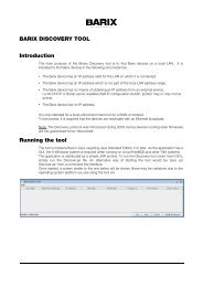
2 Running ICMASTER2.1 Booting up PS16 ICMASTERPower up the PS16. If the SonicIP is enabled, you will hear the IP which the PS16 got from yourDHCP server. After that the device will start detecting the USB stick. The following message will beshown on the PS16 LCD while the check is being performed:Checking USB sanityWhen the check was successful, the ICMASTER idle message will be displayed:IcMaster, FDX1.02 04.07.2012,16 keysIn case of broken or missing USB stick, the application will display an error message, and will exit:Bad USB stick fsIn this case, please power off the PS16, remove the two screws from the bottom, open the cover,and replace the USB stick with a new one, formatted with FAT32 file system. Also, have in mindthe following important notes:NOTE 1: If you plan to use the ICMASTER on Annuncicom 100/200, please plug in a formattedUSB stick, otherwise the application will not start.NOTE 2: Depending on your configuration, the following files may be present on your USB stick:– UNATTSND – this is the recorded unattended mode message;– CUSTMSG – this is the recorded custom message;– TEST.USB – an empty temporary file created during USB stick check;– xxx.MP3 – station ID specific ring tone files, where xxx is the station ID (for example002.mp3 is the ring tone for station ID=2).None of them is required for the application to boot, but it is advised to backup these files(without the TEST.USB as it will be deleted and recreated during boot) and copy them tothe new USB stick to keep the same configuration.2.2 PS16 Keyboard LayoutThe PS16 Paging main unit has 16 functional buttons, a flexible microphone, speaker, and 2 lineLCD. Optional extensions with 48 keys can be attached on the right side of the PS16 main unit.Key layout for PS16, as well as for every master device, is shown in the web UI home page, as inIllustration 1:10 Running ICMASTER
Illustration 1: ICMASTER keyboard layoutIf a PS16 extension is connected, key 17(bottom left corner) to key64 (top right) are assigned respectively to targets 17 to 64.The key functions are the following:Key 1: accept an incoming call / hang-up current call. If the master is in a call, and another client isringing, pressing this key will hang-up the current call. Pressing it once again will answer to theincoming call.In half duplex mode, this key works as a PTT key. Press and hold to answer incoming call and starttalking, release to listen. If the handsfree mode is activated, then the talk mode can be voicecontrolled. In this case the voice activation level, and the time-out are configured via the web UI.NOTE: closing the current call when there is a second incoming call is possible only in FDX mode.In HDX mode key 1 is used as a PTT key, so in this case only rejecting the incoming call ispossible.Key 2: page all selected clients if no call is in progress / trigger the connected client's relay (dooropen) for 5 seconds if a call is in progress. Please note this is a PTT (Push-To-Talk) button whenthe handsfree mode is not activated. In handsfree mode, press this key once to activate the pagingmode, and once again to stop it. The key LED blinks when paging is active.Key 3: pressing this key will cancel an incoming call (either in idle mode, or when the ICMASTER isin a call session with one client, and another client is calling). If the ICMASTER is in a call and thereis no other incoming call, pressing this key will also hang-up the current call session.Key 4: enter unattended mode, (pressing any other key exits unattended mode). Clients that try tocall a master that is in unattended mode will have the 'unattended message' played to them andthe call will be terminated once the message has been played.Pressing and holding this key for 4 seconds will enter the master in “call reject mode”. When themaster is in this mode, and a client calls in, instead of opening a call session and sending theunattended message, it will send a special message to the client informing that it is not available. Inthis case the client should call the next master in its list.NOTE: if the ICMASTER does not cancel/answer the second call, the ICCLIENT will continueringing and hang-up automatically after a certain amount of time (configurable via the ICCLIENTweb UI).NOTE: when the unattended mode is disabled from the web UI, pressing this key puts the masterimmediately in call reject mode.Key 5: press once start recording unattended message. A second press stops the recording andsaves the message for use. An initial 'unattended message' must be recorded when thesystem is first being set up, otherwise calls will be hung up without explanation.11 Running ICMASTER
Key 6: record/page custom message. In case of any selected targets/groups broadcasts themessage, otherwise it has no effect. To record the custom message, press and hold this key,then press key 5 once. Record your message, then press again key 5 to finish.Key 7: clear current target/group selection. If the dynamic group key is also pressed, clears alsothe address bitmap assigned to it.Key 8: select/assign dynamic page group. If there is currently no address bitmap assigned, it grabsthe current selection when pressed. To clear the bitmap, press and hold this button, then press thecancel key.Key 9: select page group 1. The address bitmap assigned to this key is configured from the relatedICMASTER web UI address map configuration page.Key 10: select page group 2. The address bitmap assigned to this key is configured from therelated ICMASTER web UI address map configuration page.Key 11: select page group 3. The address bitmap assigned to this key is configured from therelated ICMASTER web UI address map configuration page.Key 12: select page group 4. The address bitmap assigned to this key is configured from therelated ICMASTER web UI address map configuration page.Key 13: select page group 5. The address bitmap assigned to this key is configured from therelated ICMASTER web UI address map configuration page.Key 14: select page group 6. The address bitmap assigned to this key is configured from therelated ICMASTER web UI address map configuration page.Key 15: select page group 7. The address bitmap assigned to this key is configured from therelated ICMASTER web UI address map configuration page.Key 16: select page group 8. The address bitmap assigned to this key is configured from therelated ICMASTER web UI address map configuration page.Keys 17-112: select client ID (17-112) .Important note !!!When the ICMASTER is run in HDX mode, pressing key 1 when there is an active call will not closeit. In HDX mode, key 1 is used as PTT (Push-To-Talk) key. When pressed, the microphone of theICMASTER is switched ON, the speaker turned OFF, while the mic of the ICCLIENT isautomatically switched OFF, and its speaker turned ON.2.3 Running ICMASTER on Annuncicom 100/200/PS1The ICMASTER can be used also on the Annuncicom 100/200 and PS1 devices with limitedfunctionality. Because on these devices there are only two available keys, the key mapping is a bitdifferent than the one described for the PS16:Full duplex (FDX) mode:Key I: answer incoming/Close current call.Key2: if it is in a call, pressing this key will open the relay on the client for 5 seconds. When the12 Running ICMASTER
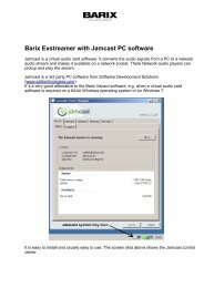
ICMASTER is in idle mode, pressing key 2 will start paging to Group 1.Half duplex (HDX) mode:Key 1: answer incoming call. While the call is active, it works as a PTT key – press and hold to talk,release to listen.Key2: if it is in a call, pressing this key will open the relay on the client for 5 seconds. When theICMASTER is in idle mode, pressing key 2 will start paging to Group 1Press and hold key 1, then press key 2: Close the current call.In addition, as the PS1 device does not have USB port, all features that use it are disabled(customized station ring-tones, unattended mode and custom messages recording).2.4 ICMASTER Web home pageThe device home page is dynamically auto-refreshed every second and shows some useful runtimeapplication details.Illustration 2: ICMASTER home pageUnder the “APPLICATION STATUS” section is visible the BARP station ID and the currentapplication status.Under the “AUDIO LEVELS” section input and output audio levels are displayed, in dB.The section “KEYBOARD LAYOUT” shows the layout of the keys, as supported and used in thecurrent hardware.2.5 ICMASTER Web configuration pagesThe configuration of the ICMASTER is very intuitive and easily done via the web UI. Examplesnapshots of the basic settings and advanced settings pages are shown on Illustration 3 andIllustration 7.13 Running ICMASTER
2.5.1 BASIC SETTINGSThe BASIC SETTINGS page is accessible clicking the CONFIGURATION button in the top menu, itshows the most important options to be set up for a quick configuration.Illustration 3: ICMASTER basic settings page• BARP Station ID• Duplex Mode• Hands Free• Group 1 Address MapEnter here the BARP system ID of this master station. The ID is used from theclients to identify the source of the control messages in multimaster environment.Default is “1001”.Choose the desired mode of operation.Default setting is "Full".When set to yes, and HDX mode is enabled, the talk/listen mode can be voicecontrolled while the ICMASTER is in active call. If the voice level exceeds the oneset in "Input Trigger Level", the master is switched in talk mode, and the client inlisten mode. The behavior for paging is also changed: the Page key needs to bepressed once (instead of press and hold) to activate Paging mode, and pressedagain to stop.Default setting is "No".Allows to set up the first group (1) of destination targets. Click related“View/Modify” button to setup the group. A label on the right shows the number ofselected clients in this group.Default setting is "id’s 1 to 10 selected".14 Running ICMASTER
2.5.2 ADVANCED SETTINGSIllustration 4: ICMASTER advanced settings pageThe ADVANCED SETTINGS page is accessible by clicking the “Advanced Settings” button in theleft menu, it contains and allows to configure all the application options, organized in specificsubsections. The advanced settings page shows all the configurable options.2.5.2.1 Network• Use SonicIP• IP Address• Netmask• Gateway IP AddressIf set to "yes", the device will announce its IP address over the audio output whenthe device boots up.Default setting is: "yes”Enter the 4 values of the desired device IP address e.g.: "0.0.0.0" for automaticdiscovery (DHCP/Bootp, IPzator, AutoIP), or a specific IP for an internal LAN.Default value: "0.0.0.0"Enter the 4 values of the desired Static IP e.g.:"0.0.0.0" for a default Netmaskdepending on the used IP Address. "255.255.255.0" for a C class networkEnter the 4 values of the desired Gateway IP address e.g.: "0.0.0.0" for noGateway, or the IP of the gateway in your LANNote: The Gateway has to be set only when connecting to other devices over theWAN (through a router).Default: "0.0.0.0"15 Running ICMASTER
• Primary DNS• Alternative DNS• Syslog Address• DHCP Host Name• Web server port• Default Ethernet Port• SNMP System NameIn this field you can give the desired primary and alternative DNS IP address to beable to connect to URLs (e.g. www.radio.com). Example: "195.186.1.111"Default: "0.0.0.0"In this field you can type the desired alternative DNS IP address in case theprimary DNS is not reachable.Example: "195.186.4.111"Default: "0.0.0.0".Destination address for syslog messages sent by the BCL program via theSYSLOG command. Set this to your syslog logging machine, if your syslogmessages are recorded centrally.If set to 0.0.0.0, syslog messages are broadcasted.Default: "0.0.0.0".Name of the device sent in DHCP request. If left empty, a name based on thedevice's MAC address is generated automatically. Enter up to 15 Characters.Defines the port where the webserver of the device can be reached. If set to "0"the default HTTP port (80) is used.On devices with dual-ethernet connection this parameter selects the default portto be used. In most cases selecting ETH1 is suitable, however some devices (e.g.the PS16) provide Power-over-Ethernet (PoE) functionality on ETH2.If you change this parameter do not forget to connect the ethernet cable to theproper port on the rear of the device.NOTE: on devices with a single ethernet port select always ETH1. Selecting ETH2makes the device inaccessible!Default: "ETH1".SNMP MIB entry for system name (system.sysName.0).Default : empty.• SNMP System LocationSNMP MIB entry for system location (system.sysLocation.0).Default : empty.16 Running ICMASTER
• SNMP System Name2.5.2.2 BARP Control• BARP Station ID• Paging PrioritySNMP MIB entry for system contact (system.sysContact.0)This parameter can be queried using any SNMP browser but can not be updated.Default : empty.Enter here the BARP system ID of this master station. The ID is used from theclients to identify the source of the control messages in multimaster environment.Default is “1001”.Enter here the priority of the audio messages sent by this master station. Thissetting is useful in multimaster environment when a client receives audiomessages from many masters simultaneously. In this case the client will play thestream with the highest priority.The priority must be in the range [1-254]. Priority "0" (the highest) is reserved foremergency priority port, priority "255" (the lowest) is reserved for BGM.Default setting is "127".• BARP Broadcast Address• BARP Audio Port• BARP Control Port• BARP Status Port2.5.2.3 Audio• Audio FormatBy default the ICCLIENT uses a broadcast IP to listen/send on the BARP ports.Modify the BARP IP address to use multicast if communication across differentnetworks is desired, or if your LAN policy is not allowing broadcast.Default setting is "0.0.0.0" (broadcast).Enter the BARP port number to which the master will send audio for paging andestablished calls. In the multicast port and address are configured, this port will beused only for incoming calls. Paging will be done using the multicast group.Default is "5555".Enter the BARP port number to which the master will send control messages.Default is "5556".Enter the destination port number where the master will listen for BARP statusmessages.Default is "5557".17 Running ICMASTER
• Input Source• Duplex Mode• Hands Free• Input Trigger Level• Inactivity timeout• Microphone Gain• A/D Amplifier GainChoose between different encoding types and sampling frequencies ("µ-law" or"A-law" at 8 or 24 kHz).Default setting is "µ-law 8 kHz".IMPORTANT: If you change the encoding don't forget to provide/record correctunattended/custom audio message files! Also, make sure to use the sameencoding on ALL devices of the <strong>ICPAGING</strong> system.Choose the desired input source.Default setting is "Mic".Choose the desired mode of operation.Default setting is "Full".When set to yes, and Half-Duplex mode is enabled, the talk/listen mode can bevoice controlled while the ICMASTER is in active call. If the voice level exceedsthe one set in "Input Trigger Level", the master is switched in talk mode, and theclient in listen mode. The behavior for paging is also changed: the Page key needsto be pressed once (instead of press and hold) to activate Paging mode, andpressed again to stop.Default setting is "No".Triggering input audio level if "Hands Free" mode is selected. Accepted range: 0-32767.Default setting is "1000".Sending of the audio stream in “Hands Free” mode stops after this number ofmilliseconds of no input audio signal.Default setting is "1000".Microphone gain dB, increase if your microphone is too faint, decrease if it's tooloud or overdriven.Default: "21 dB".A/D converter preamplification in dB. Increase if the audio signal too faint,decrease if it's too loud or overdriven. Default: "0 dB".• Default VolumeChoose between "0%" and "100%" in 5% steps.18 Running ICMASTER
2.5.2.4 Incoming Call• Call Master byDefault: "50%".• Unattended Mode• Unattended Timer2.5.2.5 Paging• Group Address Map• Audio Multicast Socket2.5.2.6 I/O Control• Relay 1 ControlConfigures the way the master is being called. If set to "ID" then the call is ignoredif the destination ID in the call request is not the same as the one of the master.When set to "IP Address", the master reacts on unicast, or broadcasted callrequests. The destination ID check is ignored in this case.Default is "IP address".Enables or disables the unattended mode. When enabled, the "Unattended Timer"becomes visible, and can be configured. Disabling the unattended mode isrecommended when using the master in a multimaster environment because ifany of the masters is in unattended mode, it may always pickup the incoming callthus preventing the other masters to get the call. When disabled, pressing theunattended mode key enters the master in a "Call reject" modeDefault is "Enabled”.Configures the number of seconds after the device switch to "unattended mode"during a call. Minimum value allowed is 3, maximum is 60.Default is "20".Allows to set up the related group of destination targets. Click related“View/Modify” button to setup the group. A label on the right shows the number ofselected clients in this group.Note: only available groups supported from the current keyboard layout aredisplayed.Default setting is: starting from group 1, 10 clients selected for every group, forgroup 1 id’s 1 to 10 are selected, group 2 id’s 11 to 20 selected … group 8 id’s71 to 80 selected.Configures the multicast group socket, as IP:PORT, for paging. As IP, it has to bewithin the range 224.0.0.0 - 239.255.255.255. If set to "0.0.0.0", then the defaultbroadcast address is used. Port is ignored if the IP is set to "0.0.0.0" .Default is "0.0.0.0:12345" - use broadcast.Configures the relay behavior. The relay can be either off ("always off"), on while anincoming call is pending ("relay while ringing") or on while a call is in process("relay while talking").19 Running ICMASTER
• LED Status2.5.2.7 Security• Reset Function• Factory Defaults• Update Function• Set PasswordDefault is "always off".Configures the device front panel led behavior for the devices that have a ledpanel.Default is "Input State".Enable or disable the "Reset" function on the Reset button and on the WEB UI. Inorder to restart the device press the Reset button once.Default: "enabled".Enable or disable the "Factory Defaults" function on the Reset button. In order torevert all settings to factory defaults keep the Reset button pressed until the redLED starts blinking (approx. 10 seconds).Default: "enabled"Enable or disable the WEB Update function of the device. If the Update function isdisabled, the only way to update the firmware is to use the serial rescue.Default: "enabled"This is visible as long as no password is set.Enter a password (up to 25 characters) and hit the "Apply" button. After the restartyou should close the browser window and open a new browser window. You willbe asked to supply user name and password. The user name can be omitted butthe password has to be supplied in order to see the web configuration.• Old Password / New PasswordThese fields are visible as long as a password is set.To allow free access (clearing the password) enter the old password and leave thefield "New Password" empty. Enter the old password in the password field abovethe "Apply" button as well and then hit the "Apply" button.After the restart you will not be asked for user name and password anymore.To change the password enter the old password and enter the new password inthe field "New Password". Enter the old password in the password field above the"Apply" button as well and then hit the "Apply" button.After the restart you will be asked for user name and password. The user namecan be omitted but the new password has to be supplied in order to see the webconfiguration.20 Running ICMASTER
3 Running ICCLIENT3.1 About ICCLIENT3.2 Available keysThe ICCLIENT application has to be run on all client endpoints from the <strong>ICPAGING</strong> system. TheICCLIENT can play BGM and paging messages, initiate a call session to two preconfiguredICMASTER stations, and send periodically its current status. Being the slave component from themaster/slave architecture, the ICCLIENT does not have the possibility to control other devices fromthe <strong>ICPAGING</strong> system.The ICCLIENT application uses the Input 0 (key 1) and Input 1 (key 2) that are available on theconnector of the supported BARIX devices. The mapping of the keys is the following:Key 1: Call ICMASTER station 1. The id or IP of the ICMASTER station is configured via theICCLIENT web configuration page.Key 2: Call ICMASTER station 2. The id or IP of the ICMASTER station is configured via theICCLIENT web configuration page.If the ICCLIENT is configured to operate with the AIPHONE door panels, then the hardware inputsare ignored, and the key 1 press is emulated by the firmware. The IP of the ICMASTER station 1 isonly used in this case.Note: The ICCLIENT can use the HAI Volume Source Control unit together with the BARIX IRRemote Control. However, if the ICCLIENT is run on BARIX device with its own LCD display (ex.BARIX Exstreamer 110) then the VSC LCD cannot be used and stays blank.3.3 ICCLIENT Web home pageThe device home page is dynamically auto-refreshed every second and shows some usefulruntime application details.Illustration 5: ICCLIENT home pageUnder the “APPLICATION STATUS” section is visible the station ID and the current applicationstatus.21 Running ICCLIENT
Under the “AUDIO LEVELS” section input and output audio levels are displayed, in dB.3.4 ICCLIENT Web configuration pageAs in ICMASTER, the ICCLIENT application can be configured in a fast fashion. ClickingCONFIGURATION top menu button, a BASIC SETTINGS page will be displayed. All the applicationoptions are then available clicking the ADVANCED SETTINGS left-menu button.3.4.1 BASIC SETTINGSThe BASIC SETTINGS page is accessible clicking the CONFIGURATION button in the top menu, itshows the most important options to be set up for a quick configuration.Illustration 6: ICCLIENT <strong>Application</strong> “basic settings” Web Page• BARP Station ID• Duplex Mode• Use AI_Phone3.4.2 ADVANCED SETTINGSThe system ID of this client station. The ID is used to identify the unit at the masterstation.Default setting is "1".Choose the desired mode of operation. If “Half” is selected, the communication iscontrolled from the ICMASTER.Default setting is "Full".This setting is for Annuncicom 200 hardware only, which provides support for AIPHONE two wire interface. Set to "Yes" if AI_Phone is used as a door station. Inthis case “Half” operating mode is recommended.Default setting is "No".The ADVANCED SETTINGS page is accessible clicking the “Advanced Settings” button inthe left-side menu.22 Running ICCLIENT
Illustration 7: ICCLIENT <strong>Application</strong> “advanced settings” Web Page3.4.2.1 NetworkThis section is the same as in ICMASTER. See ICMASTER2.5.2.1 Network section.3.4.2.2 BARP Control• BARP Station IDThe system ID of this client station. The ID is used to identify the unit at the masterstation.Default setting is "1".• BARP Broadcast Address• BARP Audio Port• BARP Control Port• BARP Status PortBy default the ICCLIENT uses broadcast to listen/send on the BARP ports. Modifythe BARP IP address to use multicast if communication across different networksis desired, or if your LAN policy is not allowing broadcast.Default setting is "0.0.0.0".Enter the BARP port number where the ICCLIENT will listen for incoming audio.Default setting is "5555".Enter the BARP port number where the ICCLIENT will listen for BARP controlmessages.Default setting is "5556".Enter the destination port number to which the ICCLIENT will broadcast BARPstatus messages.Default setting is "5557".23 Running ICCLIENT
• Notification Port3.4.2.3 Audio• Audio FormatEnable here the usage of the notification port which the client may listen for anyincoming audio. No BARP messages are checked for this port, so any audioarriving at this port will be played immediately. This can be used as a "Broadcastto all" feature.Default setting is "No".Choose between different encoding types and sampling frequencies ("µ-law" or"A-law" at 8 or 24 kHz).Default setting is "µ-law 8 kHz".IMPORTANT: make sure to use the same encoding on ALL devices of the<strong>ICPAGING</strong> system.• Input Source• Duplex Mode• Use AI_Phone• Microphone Gain• A/D Amplifier Gain• Default Paging VolumeChoose the desired input source.Default setting is "Mic".Choose the desired mode of operation. If “Half” is selected, the communication iscontrolled from the ICMASTER.Default setting is "Full".This setting is for Annuncicom 200 hardware only, which provides support for AIPHONE two wire interface. Set to "Yes" if AI_Phone is used as a door station. Inthis case “Half” operating mode is recommended.Default setting is "No".Microphone gain dB, increase if your microphone signal is too faint, decrease if it'stoo loud or overdriven.Default: "21 dB".A/D converter preamplification in dB. Use this setting to achieve the right balanceto your connected equipment. Increase if the audio signal too faint, decrease if it'stoo loud or overdriven.Default: "0 dB".Choose between "0%" and "100%" in 5% steps.Default: "50%".24 Running ICCLIENT
• Min Paging Volume• Maximal BGM Volume3.4.2.4 Outgoing Call• Call Masters by• Master Station ID• Master Station IP• Call next Master• Auto Hang UpSet here the minimum volume with which to play paging messages. If a BGM isplaying at volume level lower than this one, it will be overloaded. BGM level isrestored after end of paging message. Choose between "0%" and "100%" in 5%steps.Default: "50%".Configure here the maximum volume for the BGM you would like the client to beable to set.Default setting is "50%".Configures the way the master stations are called. If set to "IP address", themasters are called by unicasting the call request command to the master IP. If setto "ID" then the masters are called by broadcasting the call request commandwith the destination ID=master ID. Select the needed option so see thecorresponding configuration fields.Default: "IP address".When “Call Master by BARP ID” is set, enter the system ID of the related (1 to 4)master station.The first master station is called after pressing the Button 1 (activating the firstdigital input).Default setting is "for master stations 1 to 4, respectively 1001,1002,1003,1004".When “Call Master by IP Address” is set, enter the IP address of the related (1 to4) master station. If set to zero, uses broadcast to find a master station on thelocal network.The first master station is called after pressing the Button 1 (activating the firstdigital input).Default setting is "0.0.0.0".If set to "Yes" the client is forced to call the next master in the list if the one that itis currently calling is not responding (for example because of network problems orpower failure of the master). The call to the next master is activated after the expiryif the auto hang-up timeout. In this case the call ring timer is restarted when theclient starts calling the next master.Default: "No".25 Running ICCLIENT
3.4.2.5 Background MusicConfigures the number of seconds after which the client will stop ringing if themaster is not responding. Minimum value allowed is 3, maximum is 60. Makesure this value is greater than the unattended mode timeout set for theICMASTER, otherwise the ICCLIENT will not get the unattended message fromthe ICMASTER.Default: "20".• BGM Broadcast AddressEnter the broadcast/multicast address of the background music streaming server.If set to “0.0.0.0” then broadcast is used.Default setting is "0.0.0.0".• BGM First Broadcast PortEnter the broadcast/multicast port of the first channel background musicstreaming server. The BGM streaming could be provided by multiple streamers,but they have to be configured to use consecutive port numbers. If set to "0", theBGM functionality is disabled.Default setting is "11001".• BGM Available Channels• BGM Start Channel3.4.2.6 Serial• Serial Port3.4.2.7 I/O ControlEnter the number of the available background music channels. If set to "0" andno local streamer is defined, then no BGM will be played.Default setting is "0".Enter the background music channel to start playing after a reboot. If it more thanthe available channels, it is assumed to be "0" (No BGM at startup)Default setting is "0".Selects the way the device serial port will be used. Select “VSC Panel” here touse <strong>Barix</strong> VSC accessory with this application.Default: Intercom Client Software.• Relay 1 ControlSet here the default relay behaviour. Available values are:"always off" - the relay is off in all states (idle,BGM playback,paging and intercom);"on while in a call" - the relay is normally off, but when the client is in intercomstate, the relay automatically switches on;26 Running ICCLIENT
• LED Status3.4.2.8 Security"always on, off while in a call" -this is the inverted version of "On while in a call"setting. The relay is normally switched on, and off when the client is in a intercomstate."on while in PA mode" - the relay is normally off, but when the client is receivingpaging message, the relay automatically switches on."on while receiving audio stream" - the relay is normally off, but when the client isreceiving audio stream (either in intercom, or PA mode), the relay automaticallyswitches on;Note: Please have in mind that the BARP relay control command is ignored whenthe relay is not in "always off" mode in order not to override the preconfiguredrelay behaviour.Default: "always off".Configures the device front panel led behavior for the devices that have a ledpanel.Default is "Input State".This section is the same as in ICMASTER. See ICMASTER 2.5.2.7 Security section.27 Running ICCLIENT
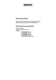
4 Running ICgraph4.1 About ICgraphICgraph is a Java-based PC software. It requires a Java Runtime Environment (JRE) installed onthe PC to run properly. Such JRE is available for almost all operating systems (seewww.java.com ). ICgraph is a free <strong>Barix</strong> software when used together with <strong>Barix</strong> hardwareproducts. This software is freely configurable over the ICgraph.cfg file. It allows to control ICPagingdevices and communicate to it.The <strong>ICPAGING</strong> firmware package contains two different ICgraph configurations, one for half-duplexand one for full-duplex. These configurations can be modified from you if needed.For more information about ICgraph check the ICgraph manual available on www.BARIX.com .4.2 How to run ICgraphThe <strong>ICPAGING</strong> software package contains a sub folder “ICgraph Master”, there are two differentICgraph configurations stored – one for full-duplex and one for half-duplex.Before you can start ICgraph, make sure the Java JRE is installed (see www.java.com ) on yourPC.If Java is installed, then decide which mode (full-duplex or half-duplex) you will use for Intercomcommunication with the clients and select the according sub directory and start the ICgraph.jar filefrom this directory.ICgraph can be used as single master or together with other Masters, but in multimaster mode thebehaviour is a little bit different than using the ICMaster devices.4.3 Usage of ICgraphThe ICgraph configuration shows per default 8 groups or 80 client (configured with Ids from 1 – 80)and some more function buttons. You can change the view and display group buttons and/or pointbuttons.Illustration 8: ICgraph application (Full-duplex)When ICPaging devices in the network are properly configured then they will be discovered aftermaximum 30 seconds from ICgraph and the according point button will change the color from28 Running ICgraph
dark grey to white. The white point buttons can be used for other actions on ICgraph. If a device isnot more reachable in the network (e.g. turned off or not connected) then the point button willchange the color of this point button from white to dark grey within 60 seconds.Buttons on ICgraph window:Show group / Show membertoggles view between point and groupIntercomallows bi-directional communication with a single point, point must request/ring before !Clear Allresets active communication and/or point buttons to normal state. Must be used to finish everycommunication from and with ICgraph.Start Paging / Stop Pagingallows to make paging/announcements to selected points and/or groups. For use this functionone, many or all points/groups should be selected before clicking the “Start Paging” button.Mute ON/ Mute OFFmutes/unmutes the ICgraph PC microphoneRelay openallows switching of the remote relay for 3 seconds on selected device. Works only during Intercommode.Menu OFF / Menu ONdisplays or hides menu/buttons below this buttonShow events / Hide eventsdisplays or hides event window, the event window is a helpful tool which shows all current pointactivitiesShow LOG / Hide LOGdisplays or hides LOG window, this window displays all ICgraph activities, even the backgroundactivitiesShow records / Hide recordsdisplays or hides Record window, this window shows all recording you made with ICgraph orfrom the sub folder “RECORDS”. From here window select recordings or self-made audio files canbe sent to the selected devices.Play message / Stop messageallows to stream a pre-recorded file to the selected points. The default message can be replaced inthe ICgraph configuration/folder . Note, the audio must be recorded in 16-bit mono WAV formatand must have the same audio frequency than ICgraph and the devices have.Start record / Stop recordthis button allows to record running communication on ICgraph. Recorded files will be displayed inRecord window. Recorded pagings to multiple points can be used to send later as pre-recordedfiles to selected devices. Note this function requires the installation of the MP3 libraries, for moreinfo see ICgraph manual.29 Running ICgraph
Settingsthis button opens on Windows PCs the Internet Explorer, if a white point button was selectedbefore then the Internet Explorer opens with the home page of the selected device.4.3.1 Intercom functionality with IcgraphIn the Full-duplex and in the Half-duplex configurations everything is the same except the Intercomfunctionality.To use the Intercom functionality the device must ring before to request the two-waycommunication. When ICgraph receives a Ring request from a device the according point buttonwill change his color and blink magenta. At this state select the point and click the Intercom buttonto get a two-way communication.In the Full-duplex mode / ICgraph configuration both sites can communicate with each other. Tofinish the communication press the “Clear All” button.In the Half-duplex mode / ICgraph configuration the Intercom button will after activation change to“Intercom Talk” (yellow) in this mode you can talk to the ringed/selected device. To listen to thedevice click on the “Intercom Talk” button. The button name will change not to “Intercom Listen”(green).Illustration 9: ICgraph half-duplex Intercom buttonsClicking on the “Intercom Listen” button with change again to “Intercom Talk button. To finish thecommunication press the “Clear All” button.Note, for Intercom only one ringing device should be selected at the same time, no Groups andnot multiple devices! If the device is not ringing anymore, then the point button will stay in magenta(none blinking). In this mode only a one-way communication (to the device) for max. 10 seconds ispossible when using the Intercom button.Illustration 10: ICgraph Point button states30 Running ICgraph
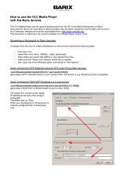
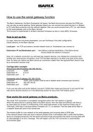
5 Implementing example paging system5.1 Necessary components5.2 System layoutFor better understanding the usage of <strong>ICPAGING</strong> solution proposed by BARIX we will try toimplement a small paging system, supporting all the advertised features. For the system shownbelow, the following components are needed:• BARIX Annuncicom 200• BARIX Annuncicom 100• AIPHONE door panel• PS16 Paging station• One PS16 48-keys extension (optional)• BARIX Exstreamer 100• A pair of powered stereo speakers• A telephone style door station• A PC for streaming music• BARIX MP3_RTP_Streamer applicationLet's implement an example system for the needs of a small shop. The proposed layout is shownon the figure below:Illustration 11: Example intercom and paging systemWe will need one Master station for sending messages, and controlling the background music, thatwill be located at the security room, one station for delivering high quality music in the shop area,31 Implementing example paging system
one door station at the stock delivery entry, and one telephone at the cash desk.The music delivery is done by a PC running the BARIX MP3_RTP_Streamer, but could be alsodone with a BARIX Instreamer device. The BGM playback can be controlled by the ICMASTER, orlocally using the HAI Volume Source Control unit.For the door station BARIX Annuncicom 200 is being used as it provides the suitable two wireinterface for connecting the AIPHONE panel. As this device is half duplex, the whole system needsto be configured in half duplex mode.5.3 Configuring the master station5.3.1 Initial setupGet the latest version of the <strong>ICPAGING</strong> ABCL software from BARIX download page. Unzip the file.Connect the ICMASTER station to the LAN, and power it on. Note down the IP addressannounced by the Sonic IP, and point the browser to that address. The application page of thePS16 will be displayed.Click on the Update tab of the current installed firmware, then click on the “Please click here tostart the update” to go to the update page.You will see the update page. Click on “Browse”, then navigate to theupdate_rescue/compound.bin in the directory where you have unzipped theabcl_icpaging_v0xxxxxx.zip file. Select it, then click on the “Upload” button to continue.Reboot the device when the update is finished, and open the web UI at the announced IP address.Once the device reboot click on DEFAULTS top menu button and apply defaults. The device willreboot again with default settings.Note: default <strong>ICPAGING</strong> running application is ICMASTER when “compound.bin” is loaded anddefaults settings are applied. The package supplied 2 additional binaries,“update_rescue/compound_master.bin” and “update_rescue/compound_client.bin”, theyrespectively contain ICMASTER or ICCLIENT as the default running application.5.3.2 General settingsIllustration 12: Device upload web pageNow it is time to configure our master station. Once PS16 is rebooted, open the Settings page andeventually set up the network settings. Network setup is not mandatory if a DHCP server/routerexists in the network, anyway, for example, a fixed IP address instead of default assigned DHCPaddress can make the device access easier in future reconfiguration operations.32 Implementing example paging system
5.3.3 ICMASTER settingsNow it is time to configure the ICMASTER specific settings. Click on the “Advanced Settings” tab,and set the following items :• Basic Settings or Audio section, Duplex ModeChoose "Half".• Paging section, Group 1 Address MapClick on the “View/Modify” button to open the address map configuration dialog,click “Clear All”, then select id 1 only and click apply. After device reboot click“Close”.• Paging section, Group 2 Address MapClick on the “View/Modify” button to open the address map configuration dialog,click “Clear All”, then select id 2 only and click apply. After device reboot click“Close”.• Paging section, Group 3 Address Map• Group 4 Address MapClick on the “View/Modify” button to open the address map configuration dialog,click “Clear All”, then select id 3 only and click apply. After device reboot click“Close”.Click on the “View/Modify” button to open the address map configuration dialog:We will dedicate this group to select all, then we need to check clients ID=1, 2and 3). So click “Clear All”, select 1, 2, and 3, then click “Apply” at the bottom ofthe Group configuration page. The device will reboot, click “Close” to exit addressmap configuration page.NB! Do the group key assignment after you have applied all other ICMASTERsettings. Otherwise the changes will be lost, and only the group mask will besaved.After reboot, click CONFIGURATION and Advanced Settings button, and check ifthe number of the selected clients for the groups is correct. It should look like this:Illustration 13: Group buttons address bitmap summaryFor more detailed explanation on the address bitmap configuration values see sectionsUnderstanding BARP address bitmaps.33 Implementing example paging system
• Paging section, Audio Multicast SocketConfigure 224.1.2.3, leave the default port as "12345".Leave all other settings to their default values, and click “Apply”. With this theICMASTER station configuration is finished.5.4 Configuring the door station5.4.1 Initial setupDo the initial setup as described in the ICMASTER General settings section. After uploading theSW, if the default running application is ICMASTER click REBOOT menu button and under the“Reboot as” drop down list select “Intercom Client” and click “Reboot”.5.4.2 General settingsNow it is time to configure our door station. As has been done for the master station, onceAnnuncicom 200 is rebooted, open CONFIGURATION and then “Advanced Settings” page andsetup the desired options int the Network Settings section.5.4.3 Door station settings• BARP Control section, BARP Station IDCheck the client ID to be "1".• Audio section, Duplex ModeChoose "Half".• Audio section, Use AI_PhoneSet to "Yes"• Background Music section, BGM First Broadcast PortPlaying music on AI_Phone is not possible because of the two line interface that itis using, so set it to "0" (no BGM).Click the “Apply” button to save the settings, and reboot the device.5.5 Configuring the cash desk station5.5.1 Initial setupDo the initial setup as described in the ICMASTER General settings section. After uploading theSW, if the default running application is ICMASTER click REBOOT menu button and under the“Reboot as” drop down list select “Intercom Client” and click “Reboot”.5.5.2 General settingsNow it is time to configure our door station. As has been done for the master station, onceAnnuncicom 100 is rebooted, open CONFIGURATION and then “Advanced Settings” page andsetup the desired options int the Network Settings section.34 Implementing example paging system
5.5.3 Cash desk settings• BARP Control section, BARP Station ID5.6 Configuring the stereo music player5.6.1 Initial setupSet the client ID "2".Click the “Apply” button to save the settings, and reboot the device.Do the initial setup as described in the ICMASTER General settings section. After uploading theSW, if the default running application is ICMASTER click REBOOT menu button and under the“Reboot as” drop down list select “Intercom Client” and click “Reboot”.5.6.2 General settingsNow it is time to configure our door station. As has been done for the master station, onceExstreamer 100 is rebooted, open CONFIGURATION and then “Advanced Settings” page andsetup the desired options int the Network Settings section.In addition, also set the serial port to be used for the VSC.• I/O Control section, Serial PortSelect “VSC Panel.”5.6.3 BGM player settings• BARP Control section, Station IDSet the client ID "3".• Background Music section, BGM Broadcast AddressSet to use multicast address 224.1.2.4.• Background Music section, BGM First Broadcast PortSet to "10501".• Background Music section, Available BGM ChannelsSet to “3”.• Background Music section, BGM Start ChannelSet to “1”.5.6.4 Connecting the Volume Source Control (VSC) unitUnpack the VSC unit from the supplied box. Turn it upside down. Take a small flat tip screwdriverand set the arrow of the yellow switch to point to “1”.Take a LAN cable with the necessary length, and plug it in the VSC RJ-45 socket.35 Implementing example paging system
Connect the other end of the LAN cable to the DSUB9-RJ45 2 adapter. Plug the adapter in the RS-232 port at the back panel of the Exstreamer 100 screwing it for more reliable connection.Reboot the Exstreamer 100 to recognise the newly connected VSC unit.Now the VSC unit should be functional. After reboot, the default BGM channel should be displayed(for.ex. “1”). Rotating the knob left/right decreases/increases the volume. Pressing the knobswitches to “channel” mode, the rotation changes the channel being played. If channel “0” isselected, and the local instreamer is enabled, then “Lo” (meaning local channel) is displayed. Incase the local instreamer is disabled, “Id” (idle) is displayed.5.7 Configuring the PC for BGM distribution5.7.1 Hardware requirementsFor music distribution we need a computer that can run the BARIX MP3_RTP_Streamerapplication which creates several streams from MP3 library. Any recent Windows/Linux/iMaccomputer running Java VM should work.5.7.2 Configuring the MP3_RTP_StreamerDownload the MP3_RTP_Streamer from the BARIX web site. Unzip it in a separate directory, andrun the MP3_RTP_Streamer.jar. The application window should look like this:Illustration 14: MP3_RTP_Streamer main window (unconfigured)We're going to configure it to play the 3 BGM channels, plus the “local” channel. The three BGMchannels will stream from ports 10501, 10502, 10503, while the local channel should beconfigured at port 10500. Double click at the MP3_RTP streamer window to open the channel adddialog:Illustration 15: MP3_RTP_Streamer configuration dialogPut the channel name first, ex. “Local channel” for channel “0”Set the IP to the multicast group 224.1.2.4, and the port to 10500Click “Music lib/dir” and navigate to the directory where your mp3 files and playlists reside.Click “Playlist” and select the playlist for this channel. The playlists can be created with iTunes,WinAmp, or any other mp3 capable player.2 This DSUB9-RJ45 adapter is sold separately. Please contact BARIX for more information.36 Implementing example paging system
Click on “Create” and repeat all these steps to add channels 1 to 3, using ports 10501 to 10503.Now the MP3_RTP_streamer is configured, and should be streaming music on address 224.1.2.4and ports 10500-105035.8 Testing the Paging system5.8.1 Recording a custom messageThe ICMASTER allows the user to pre-record an announcement to be sent when desired to theselected targets.Make sure there are no clients selected (by pressing the “Cancel Sel” key (key 7). Keep pressedthe custom message key (key 6, lcd display will show a warning "Nothing Selected"), then presskey 5 and release it to start recording (key 6 can be released from now). “Recording custommessage” will be displayed on the PS16 LCD. Press again key 5 a second time to stop recordingand save the message to the USB stick.5.8.2 Rejecting a callPress the call button on the Door, or cash desk station. Wait for the ICMASTER to display themessage with the caller ID, and play the ring tone, then press key 3 to reject the call. The clientshould play the busy tone.5.8.3 Answer a callPress again the call button on the client. When the call indication is received on the master, presskey 1, and keep it pressed for a while. As it is a PTT key, the ICCLIENT is switched to listen modewhen pressed, and to talk mode when released.Release the key to listen to the client, and push it again to talk. Press key 2 to toggle the relay onthe client, or key 3 to hang up the call5.8.4 PagingSelect the desired clients to be paged by pressing the corresponding target (group) buttons, thenpress and hold the page key (key 2) to send the message. Release it when finished.5.8.5 Paging the custom messageWith a group selection active, press the custom message key once. The prerecorded message willbe sent to the selected Ids, and once the message has been sent the ICMASTER will return to idlemode. The LED will blink while sending, and the BGM playback should be restored after themessage is sent.37 Implementing example paging system
6 Additional information6.1 Updating a device using the RS-232 serial portSometimes when the device is not accessible via the LAN, or the image in the flash memory iscorrupted for some reason, then a serial rescue may be needed to reset the device to the factorydefaults 3 .So, here are the steps that need to be executed to do the serial rescue:• Disconnect the device from the power supply• Connect the COM port of the device to the COM port of your computer via a null modemserial cable• Open a terminal in the update_rescue directory in your unzipped copy of the ABCP<strong>ICPAGING</strong> firmware. If using Linux or Mac, switch to update_rescue/linux directory• Start the rescue process by executing serialX, where X is the number (1-4) of the serialport on the computer• If running on Linux /Mac execute the seriald.sh script, giving the device name of your COMport as a parameter. For ex.:seriald /dev/tty.UC-232AC• Power on the device, and wait for the update to finish. The device will rebootautomatically.NOTE: All other settings except the network settings will be lost !6.2 Restoring Factory Defaults of PS16This new feature has been added as a software replacement for the missing reset button inPS16 stations.In some cases (forgot web UI password, loading corrupted FW image, etc.) the access to theweb UI of the ICMASTER may be lost. In such a situation the one of the possible recoverysolutions on the BARIX devices is to press and hold the reset button while powered on 4 . Thedevice will revert to factory defaults, and reboot.However, since PS16 stations do not have HW reset button, this procedure is not applicable.In this case follow the procedure below to revert to factory defaults:• Press and hold key 1 (lower left) at startup. A message will appear on the displayasking you to confirm;• To confirm press key 16 (upper right) within 3 seconds, without releasing key 1,3 Rescuing the PS16 using the serial port is more complex, and requires some engineering work. Pleasecontact BARIX Support to get more information.4 Another recovery solution is to do a serial rescue using the serial port (see section ). Updating a diveceusing RS-232 serial port38 Additional information
otherwise the unit will continue booting normally;• After confirming and releasing all keys, the factory defaults are restored and the unitreboots. Listen to the SonicIP and note down the IP address.• Open the web page at the announced IP address, and change the application from“ICCLIENT” to “ICMASTER”. Click “Apply to reboot.After reboot, reconfigure the ICMASTER as it was before.6.3 Configuring <strong>ICPAGING</strong> in multimaster environmentIn some cases, multiple masters may be needed in the paging system. For example, a door stationmay need to ring to the reception at the entrance during normal working hours, and to the securityroom at night.For this purpose, <strong>ICPAGING</strong> supports several multimaster scenarios:6.3.1 Call Failover scenario:In this case maximum 4 masters can be called by the client. If one of the first two masters in theclient IP/ID list are called, and it is in "call reject mode" then the client starts calling the other threemasters in a chain. However, if the first master does not reply (or any other master called in thechain) then the client will timeout, and may not connect to any master. To prevent this happen, the"Call next Master" on the client must be enabled.6.3.2 Call all masters scenarioFor that mode the masters must be addressed by IP. This is done by setting the ICCLIENT CallMasters by and the ICMASTER Call Master by configuration options to “IP Address”.Then it is enough to set one of the first two master IP addresses in the ICCLIENT list to IP address0.0.0.0. In this case, when the call button associated with that IP address is pressed, then the callrequest is broadcasted to all masters, and one of them may pickup. The masters track the currentstate of the calling client status message, and if it changes to something other that 3 (connecting)then they stop ringing. The masters also stop ringing if more than 5 seconds have elapsed after thelast call request command, sent from the client.6.3.3 Call all + failover scenario:Configured as call all masters scenario. However, if there is one master in a call reject mode, theclient will get the reject and start calling the other masters in the list by sending unicast callrequests. The masters that got the broadcasted call request shall stop ringing.6.4 Understanding BARP address bitmapsAccording to BARP protocol, the address bitmap is 128 bytes, allowing to address client IDs 1-1024 (starting from "1", client ID=0 is not valid). In the ICMASTER application, because of thelimited memory space in the EEPROM only the first 16 bytes can be stored, thus allowing to groupselect only the first 128 client IDs.Each byte addresses 8 clients (for ex. byte 0 addresses clients IDs 1-8, byte 1 addresses client IDs9-16, etc.) Setting a bit within a byte enables the corresponding client, clearing the bit-disables it.However, the client IDs within a byte are stored in reversed order, i.e. the smallest ID is stored in theMSB, the biggest at the LSB. The composed address map is then transmitted with the smallest39 Additional information
yte numbers first, as shown on the picture below:Byte0 Byte 127Client Ids 1-8 (bits 7-0) Client Ids 1017-1024 (bits 7-0)Bits 7 6 5 4 3 2 1 0 ........ 7 6 5 4 3 2 1 0Client ID 1 2 3 4 5 6 7 8 ........ 1017 1018 1019 1020 1021 1022 1023 1024Enable/Disable 1 0 1 0 1 0 1 0 ........ 0 0 0 0 0 0 0 0Hex A A 0 0Illustration 16: Address bitmap encodingTo find out in which byte is the client ID we would like to select, we use the integer divisionoperation:IDbyte=Client ID−1/8Let's see what it means in terms of our example. Let's find in which byte is our client ID 21:Idbyte=(21-1)/8=2The result is the biggest number, which multiplied by 8 does not exceed (ID-1). The other resultfrom this operation is called reminder, and is in fact the number that completes to ID-1:ID-1 = result*8 + reminderNow, to find which bit within this byte, we take the reminder (which for ID-21 is 4) from the integerdivision, and subtract it from 7. In other words:IDbit =7 – 4 = 3which means that we have to set bit3 from byte2:Byte0 Byte1 Byte2Client Ids 1-8 Client Ids 9-16 Client Ids 17-24Bits 7 6 5 4 3 2 1 0 7 6 5 4 3 2 1 0 7 6 5 4 3 2 1 0Enable/Disable 0 0 0 0 0 0 0 0 0 0 0 0 0 0 0 0 1 0 0 0 1 0 0 0Hex 0 0 0 0 8 8Repeating these calculations for client ID=17, we find that bit7 of byte2 has to be set. Looking atthe 6.5 BIN / DEC / HEX conversion table, we see that 1000 is 0x8 in HEX format, which explainsthe 0x88 value we see for group 1 in the Group buttons address bitmap summary.6.5 BIN / DEC / HEX conversionHexadecimal digits have values from 0..15, represented as 0..9 and as A (for 10) to F (for 15).The following table can serve as a conversion chart:Bin /DEC / Hex TableDecimal Binary Hexadecimal0 0000 01 0001 12 0010 23 0011 34 0100 45 0101 56 0110 640 Additional information
Decimal Binary Hexadecimal7 0111 78 1000 89 1001 910 1010 A11 1011 B12 1100 C13 1101 D14 1110 E15 1111 FTo convert a binary value in a hexadecimal representation, the upper and lower four bits are treatedseparately, resulting in a two-digit hexadecimal number.41
7 TroubleshootingBelow just a brief table to help solving the main known issues.1SSUE DescriptionPossible cause and remedy action1Device boot but web UIhome page frames showsERROR 400.<strong>ICPAGING</strong> has been uploaded over an existing differentABCL fw based application.Click “DEFAULTS” on the top menu and apply defaults.2Device not visible in theLAN network.An IP assignment server is missing in the LAN, or therecould be a LAN cable issue.Check device LAN cable connections, eventually setfirmware defaults through keeping pressed the device frontpanel reset button for more than 10 seconds, then listen toSonicIP.If the above don’t solve the issue try the serial rescueprocess (see par. Fehler: Referenz nicht gefunden).3 Audio is missing.Volume level is set to 0, mic or speakers wiring is defective.Check the volume level, (client Audio >Default PagingVolume, master Audio > Default Volume fields), to be greaterthan 0. Check also mic and speakers to be well connectedto the device.4 Audio corrupted.Client device has an audio format set different from themaster.Check “Audio Format” field, under CONFIGURATION >Advanced Settings > Audio section. All devices in thesystem MUST have the same audio format set.5Annuncicom 100/200master device notworking.USB key is not connected to the device.Insert a USB key.67ICCLIENT locked in“PAGING” state.Device not responding inthe serial update process.Master could have been rebooted while paging.Once master is up, re-page locked devices and close thepaging session.Another PC task can be holding the serial port.Check for other PC programs/tasks using the same serialport and terminate them. Restart the update procedure.42 Troubleshooting
8 Dictionary8.1.1 DHCPShort for Dynamic Host Configuration Protocol, a protocol used to assign an IP address to adevice connected to a Network.8.1.2 FDXShort for Full Duplex. A full-duplex system allows communication between two parties to be donein both directions simultaneously. See this Wikipedia article for more information.8.1.3 HDXShort for Half Duplex. In a half-duplex system simultaneous communication in both directions isnot possible, i.e. if one of the parties is sending, the other have to wait it to finish before replying.See this Wikipedia article for more information.8.1.4 IPShort for Internet Protocol, the IP is an address of a computer or other network device on anetwork using IP or TCP/IP. Every device on an IP-based network requires an IP address to identifyits location or address on the network. Example: 192.168.2.108.1.5 IPzator<strong>Barix</strong> IPzator technology is designed for the purpose that the <strong>Barix</strong> device can create its own IPaddress according to the network structure in case it can’t receive one from your network. IfDHCP, AUTOIP or BOOTP fail, IPzator will create an IP address within the subnet and test it(starting with x.x.x.168 and if occupied incrementing by one). If the address works and is not beingused by another device on the network, it will give the address to the <strong>Barix</strong> device.8.1.6 MAC addressAbbreviation for Medium Access Control, a MAC is a unique address number formatted inhexadecimal format and given to each computer and/or network device on a computer network.Because a MAC address is a unique address a computer network will not have the same MACaddress assigned to more than one computer or network device. Example: A1:B2:C3:D4:E5:F68.1.7 NetmaskA number used to identify a sub network so that an IP address can be shared on a LAN (LocalArea Network).A mask is used to determine what subnet an IP address belongs to. An IP address has twocomponents, the network address and the host address. For example, consider the IP address150.215.017.009. Assuming this is part of a Class B network, the first two numbers (150.2.)represent the Class B network address, and the second two numbers (.017.009) identify aparticular host on this network.The Netmask would then be 255.255.0.0 .8.1.8 Static IPA Static IP is a fixed IP address that you assign manuallyto a device on the network. It remains valid until you disable it.43 Dictionary
8.1.9 VSCVolume Source Control unit. This an universal wall mountable control accessory for the <strong>Barix</strong> audioproducts range. It provides two digit LED display, control knob, and a IR port.8.1.10 IP AddressingAn IP address is a 32 bit value, divided into four octets of eight bits each. The standardrepresentation is four decimal numbers (in the range of 0..255), divided by dots.• Example: 192.2.1.123This is called decimal-dot notation. The IP address is divided in two parts: a network and a hostpart. To support different needs, five ”network classes” have been defined. Depending on thenetwork class, the last one, two or last three bytes define the host, while the remaining part definesthe network. In the following text, ‘x’ stands for the host part of the IP address.8.1.11 Class A network• IP address 1.x.x.x to 127.x.x.xOnly 127 different networks of this class exist. These have a very large number of potentialconnected devices (up to 16'777'216)• Example: 10.0.0.1 (network 10, host 0.0.1)8.1.12 Class B network• IP address 128.0.x.x to 191.255.x.xThese networks are used for large company networks. Every network can consist of up to 65534devices.• Example: 172.1.3.2 (network 172.1, host 3.2)8.1.13 Class C network• IP address 192.0.0.x to 223.255.255.xClass C networks are most common and for smaller companies. These networks can consist of amaximum number of 254hosts.• Example: 192.7.1.9 (network 192.7.1, host 9)8.1.14 Class D networkThe remaining addresses 224.x.x.x - 239.x.x.x are defined as ”Class D” and are used as multicastaddresses.8.1.15 Class E networkNo addresses are allowed with the four highest order bits set to “1” (240.x.x.x – 254.x.x.x).These addresses, called "class E", are reserved.44 Dictionary
8.1.16 Network AddressThe host address with all host bits set to "0" is used to address the network as a whole (forexample in routing entries).• Example: 192.168.0.0Network addresses can not be used as a host address!8.1.17 Broadcast AddressThe address with the host part bits all set to ”1” is the broadcast address, meaning ”for everyhost”.• Example: 192.168.0.255Broadcast addresses can not be used as a host address!8.1.18 IP NetmaskThe Netmask is used to divide the IP address differently from the standard defined by the classesA,B and C.Entering a Netmask, it is possible to define how many bits from the IP address are to be taken asthe network part and how many bits are to be taken as the host part.Standard IP network Netmask:Class Network bits Host bits NetmaskA 8 24 255.0.0.0B 16 16 255.255.0.0C 24 8 255.255.255.0Netmask examples:NetmaskHost bits255.255.255.252 2255.255.255.248 3255.255.255.240 4255.255.255.224 5255.255.255.192 6255.255.255.128 7255.255.255.0 8255.255.254.0 9255.255.252.0 10255.255.248.0 1145 Dictionary
Netmask. .. .Host bits255.128.0.0 23255.0.0.0 248.1.19 Private IP Networks and the InternetIf your network is not connected to the Internet and there are no plans to make such a connectionyou may use any IP address you wish.However if you are not connected to the Internet and have plans to connect to the Internet or youare connected to the Internet and want to operate your <strong>Barix</strong> Barionet on an intranet you shoulduse one of the sub-networks below for your network. These network numbers have been reservedfor such networks. If you have any questions about IP assignment ask your Network Administrator.Private IP networks by class:ClassABCNetwork10.x.x.x172.16.x.x192.168.0.x8.1.20 Network RFC’sFor more information regarding IP addressing see the following documents. They can be found onthe Internet:RFCDescription950 Internet Standard Subnetting Procedure1700 Assigned Numbers1117 Internet Numbers1597 Address Allocation for Private Internets46 Dictionary
9 Legal Information© 2012 <strong>Barix</strong> AG, Zurich, Switzerland.All rights reserved.All information is subject to change without notice.All mentioned trademarks belong to their respective owners and are used for reference only.<strong>Barix</strong> and <strong>ICPAGING</strong> are trademarks of <strong>Barix</strong> AG, Switzerland and are registered in certaincountries. For information about our devices and the latest version of this manual please visitwww.barix.com.Illustration IndexIllustration 1: ICMASTER keyboard layout...........................................................................................................11Illustration 2: ICMASTER home page..................................................................................................................13Illustration 3: ICMASTER basic settings page.....................................................................................................14Illustration 4: ICMASTER advanced settings page..............................................................................................15Illustration 5: ICCLIENT home page....................................................................................................................21Illustration 6: ICCLIENT <strong>Application</strong> “basic settings” Web Page..........................................................................22Illustration 7: ICCLIENT <strong>Application</strong> “advanced settings” Web Page...................................................................23Illustration 8: ICgraph application (Full-duplex)....................................................................................................29Illustration 9: ICgraph half-duplex Intercom buttons............................................................................................31Illustration 10: ICgraph Point button states.........................................................................................................31Illustration 11: Example intercom and paging system.........................................................................................32Illustration 12: Device upload web page.............................................................................................................33Illustration 13: Group buttons address bitmap summary....................................................................................34Illustration 14: MP3_RTP_Streamer main window (unconfigured).......................................................................37Illustration 15: MP3_RTP_Streamer configuration dialog....................................................................................37Illustration 16: Address bitmap encoding............................................................................................................41<strong>Barix</strong> AGSeefeldstrasse 3038008 ZürichSWITZERLANDT +41 43 433 22 11F +41 44 274 28 49www.barix.comsales@barix.comsupport@barix.com47 Legal Information