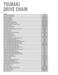
Conveyor Chain - Tsubaki
Conveyor Chain - Tsubaki
Conveyor Chain - Tsubaki
- No tags were found...

Create successful ePaper yourself
Turn your PDF publications into a flip-book with our unique Google optimized e-Paper software.
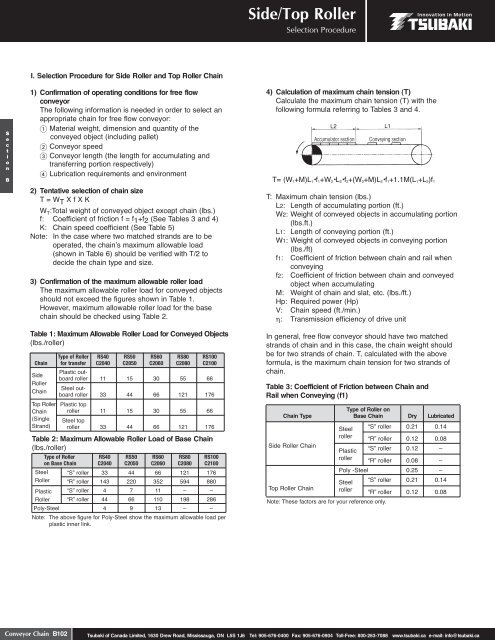
Side/Top RollerSelection ProcedureI. Selection Procedure for Side Roller and Top Roller <strong>Chain</strong>SectionB1) Confirmation of operating conditions for free flowconveyorThe following information is needed in order to select anappropriate chain for free flow conveyor: Material weight, dimension and quantity of theconveyed object (including pallet) <strong>Conveyor</strong> speed <strong>Conveyor</strong> length (the length for accumulating andtransferring portion respectively) Lubrication requirements and environment2) Tentative selection of chain sizeT = W T X f X KW T :Total weight of conveyed object except chain (lbs.)f: Coefficient of friction f = f1+f2 (See Tables 3 and 4)K: <strong>Chain</strong> speed coefficient (See Table 5)Note: In the case where two matched strands are to beoperated, the chainʼs maximum allowable load(shown in Table 6) should be verified with T/2 todecide the chain type and size.3) Confirmation of the maximum allowable roller loadThe maximum allowable roller load for conveyed objectsshould not exceed the figures shown in Table 1.However, maximum allowable roller load for the basechain should be checked using Table 2.Table 1: Maximum Allowable Roller Load for Conveyed Objects(lbs./roller)Type of Roller RS40 RS50 RS60 RS80 RS100<strong>Chain</strong> for transfer C2040 C2050 C2060 C2080 C2100SideRoller<strong>Chain</strong>Top Roller<strong>Chain</strong>(SingleStrand)Plastic outboardroller 11 15 30 55 66Steel outboardroller 33 44 66 121 176Plastic toproller 11 15 30 55 66Steel toproller 33 44 66 121 176Table 2: Maximum Allowable Roller Load of Base <strong>Chain</strong>(lbs./roller)Type of Roller RS40 RS50 RS60 RS80 RS100on Base <strong>Chain</strong> C2040 C2050 C2060 C2080 C2100SteelRollerPlasticRoller“S” roller“R” roller“S” roller“R” roller33143444442207666635211110121594–198176880–286Poly-Steel 4 9 13 – –Note: The above figure for Poly-Steel show the maximum allowable load perplastic inner link.4) Calculation of maximum chain tension (T)Calculate the maximum chain tension (T) with thefollowing formula referring to Tables 3 and 4.Accumulator sectionConveying sectionT= (W 1+M)L 1•f 1+W 2•L 2•f 2+(W 2+M)L 2•f 1+1.1M(L 1+L 2)f 1T: Maximum chain tension (lbs.)L2: Length of accumulating portion (ft.)W2: Weight of conveyed objects in accumulating portion(lbs.ft.)L1: Length of conveying portion (ft.)W1: Weight of conveyed objects in conveying portion(lbs./ft)f1: Coefficient of friction between chain and rail whenconveyingf2: Coefficient of friction between chain and conveyedobject when accumulatingM: Weight of chain and slat, etc. (lbs./ft.)Hp: Required power (Hp)V: <strong>Chain</strong> speed (ft./min.)η: Transmission efficiency of drive unitIn general, free flow conveyor should have two matchedstrands of chain and in this case, the chain weight shouldbe for two strands of chain. T, calculated with the aboveformula, is the maximum chain tension for two strands ofchain.Table 3: Coefficient of Friction between <strong>Chain</strong> andRail when Conveying (f1)Type of Roller on<strong>Chain</strong> Type Base <strong>Chain</strong> Dry LubricatedSide Roller <strong>Chain</strong>Top Roller <strong>Chain</strong>Note: These factors are for your reference only.Steel “S” roller 0.21 0.14roller “R” roller 0.12 0.08Plastic “S” roller 0.12 –roller “R” roller 0.08 –Poly -Steel 0.25 –Steel “S” roller 0.21 0.14roller “R” roller 0.12 0.08<strong>Conveyor</strong> <strong>Chain</strong> B102<strong>Tsubaki</strong> of Canada Limited, 1630 Drew Road, Mississauga, ON L5S 1J6 Tel: 905-676-0400 Fax: 905-676-0904 Toll-Free: 800-263-7088 www.tsubaki.ca e-mail: info@tsubaki.ca