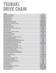
Conveyor Chain - Tsubaki
Conveyor Chain - Tsubaki
Conveyor Chain - Tsubaki
- No tags were found...

Create successful ePaper yourself
Turn your PDF publications into a flip-book with our unique Google optimized e-Paper software.
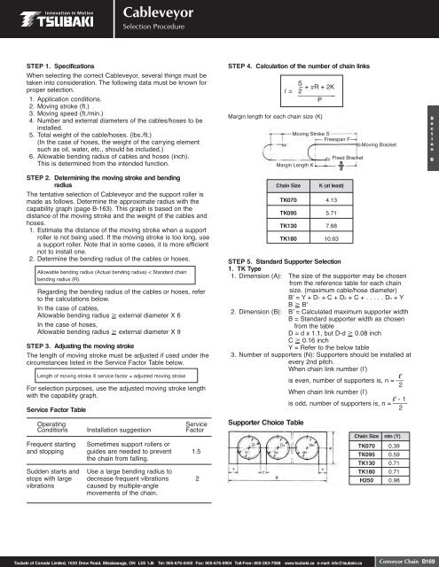
CableveyorSelection ProcedureSTEP 1. SpecificationsWhen selecting the correct Cableveyor, several things must betaken into consideration. The following data must be known forproper selection.1. Application conditions.2. Moving stroke (ft.)3. Moving speed (ft./min.)4. Number and external diameters of the cables/hoses to beinstalled.5. Total weight of the cable/hoses. (lbs./ft.)(In the case of hoses, the weight of the carrying elementsuch as oil, water, etc., should be included.)6. Allowable bending radius of cables and hoses (inch).This is determined from the intended function.STEP 2. Determining the moving stroke and bendingradiusThe tentative selection of Cableveyor and the support roller ismade as follows. Determine the approximate radius with thecapability graph (page B-163). This graph is based on thedistance of the moving stroke and the weight of the cables andhoses.1. Estimate the distance of the moving stroke when a supportroller is not being used. If the moving stroke is too long, usea support roller. Note that in some cases, it is more efficientnot to install one.2. Determine the bending radius of the cables or hoses.Allowable bending radius (Actual bending radius) < Standard chainbending radius (R).Regarding the bending radius of the cables or hoses, referto the calculations below.In the case of cables,Allowable bending radius external diameter X 6In the case of hoses,Allowable bending radius external diameter X 9STEP 3. Adjusting the moving strokeThe length of moving stroke must be adjusted if used under thecircumstances listed in the Service Factor Table below.Length of moving stroke X service factor = adjusted moving strokeFor selection purposes, use the adjusted moving stroke lengthwith the capability graph.Service Factor TableOperatingServiceConditions Installation suggestion FactorFrequent starting Sometimes support rollers orand stopping guides are needed to prevent 1.5the chain from falling.Sudden starts and Use a large bending radius tostops with large decrease frequent vibrations 2vibrationscaused by multiple-anglemovements of the chain.STEP 4. Calculation of the number of chain linksMargin length for each chain size (K)<strong>Chain</strong> SizeK (at least)STEP 5. Standard Supporter Selection1. TK Type1. Dimension (A): The size of the supporter may be chosenfrom the reference table for each chainsize. (maximum cable/hose diameter)Bʼ = Y + D1 + C + D2 + C + . . . . . Dn + YB Bʼ2. Dimension (B): Bʼ = Calculated maximum supporter widthB = Standard supporter width as chosenfrom the tableD = d x 1.1, but D-d 0.08 inchC 0.16 inchY = Refer to the below table3. Number of supporters (N): Supporters should be installed atevery 2nd pitch.When chain link number (lʼ)lʼis even, number of supporters is, n = –– 2When chain link number (lʼ)lʼ - 1is odd, number of supporters is, n = ––––2Supporter Choice TableS – + R + 2Kl = 2 ––––––––– –PMoving Stroke SFreespan FMargin Length KTK070 4.13TK095 5.71TK130 7.68TK180 10.63Fixed Brackets2Moving Bracket<strong>Chain</strong> Sizemin (Y)TK070 0.39TK095 0.59TK130 0.71TK180 0.71H250 0.98SectionB<strong>Tsubaki</strong> of Canada Limited, 1630 Drew Road, Mississauga, ON L5S 1J6 Tel: 905-676-0400 Fax: 905-676-0904 Toll-Free: 800-263-7088 www.tsubaki.ca e-mail: info@tsubaki.ca<strong>Conveyor</strong> <strong>Chain</strong> B169