

Journal of Emerging Technologies in Web Intelligence Contents
Journal of Emerging Technologies in Web Intelligence Contents
Journal of Emerging Technologies in Web Intelligence Contents

You also want an ePaper? Increase the reach of your titles
YUMPU automatically turns print PDFs into web optimized ePapers that Google loves.
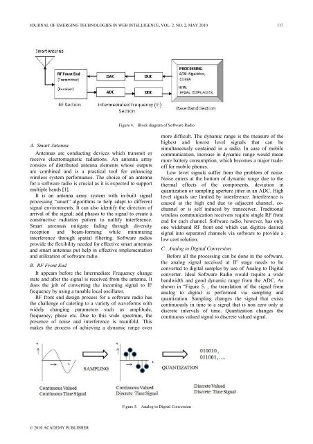
JOURNAL OF EMERGING TECHNOLOGIES IN WEB INTELLIGENCE, VOL. 2, NO. 2, MAY 2010 117Figure 4. Block diagram <strong>of</strong> S<strong>of</strong>tware RadioA. Smart AntennaAntennas are conduct<strong>in</strong>g devices which transmit orreceive electromagnetic radiations. An antenna arrayconsists <strong>of</strong> distributed antenna elements whose outputsare comb<strong>in</strong>ed and is a practical tool for enhanc<strong>in</strong>gwireless system performance. The choice <strong>of</strong> an antennafor a s<strong>of</strong>tware radio is crucial as it is expected to supportmultiple bands [1].It is an antenna array system with <strong>in</strong>-built signalprocess<strong>in</strong>g “smart” algorithms to help adapt to differentsignal environments. It can also identify the direction <strong>of</strong>arrival <strong>of</strong> the signal; add phases to the signal to create aconstructive radiation pattern to nullify <strong>in</strong>terference.Smart antennas mitigate fad<strong>in</strong>g through diversityreception and beam-form<strong>in</strong>g while m<strong>in</strong>imiz<strong>in</strong>g<strong>in</strong>terference through spatial filter<strong>in</strong>g. S<strong>of</strong>tware radiosprovide the flexibility needed for effective smart antennasand smart antennas put help <strong>in</strong> effective implementationand utilization <strong>of</strong> s<strong>of</strong>tware radio.B. RF Front EndIt appears before the Intermediate Frequency changestate and after the signal is received from the antenna. Itdoes the job <strong>of</strong> convert<strong>in</strong>g the <strong>in</strong>com<strong>in</strong>g signal to IFfrequency by us<strong>in</strong>g a tunable local oscillator.RF front end design process for a s<strong>of</strong>tware radio hasthe challenge <strong>of</strong> cater<strong>in</strong>g to a variety <strong>of</strong> waveforms withwidely chang<strong>in</strong>g parameters such as amplitude,frequency, phase etc. Due to this wide spectrum, thepresence <strong>of</strong> noise and <strong>in</strong>terference is manifold. Thismakes the process <strong>of</strong> achiev<strong>in</strong>g a dynamic range evenmore difficult. The dynamic range is the measure <strong>of</strong> thehighest and lowest level signals that can besimultaneously conta<strong>in</strong>ed <strong>in</strong> a radio. In case <strong>of</strong> mobilecommunication, <strong>in</strong>crease <strong>in</strong> dynamic range would meanmore battery consumption, which becomes a major trade<strong>of</strong>ffor mobile phones.Low level signals suffer from the problem <strong>of</strong> noise.Noise enters at the bottom <strong>of</strong> dynamic range due to thethermal effects <strong>of</strong> the components, deviation <strong>in</strong>quantization or sampl<strong>in</strong>g aperture jitter <strong>in</strong> an ADC. Highlevel signals are limited by <strong>in</strong>terference. Interference iscaused at the high end due to adjacent channel, cochannelor is self <strong>in</strong>duced by transceiver. Traditionalwireless communication receivers require s<strong>in</strong>gle RF frontend for each channel. S<strong>of</strong>tware radio, however, has onlyone wideband RF front end which can digitize desiredsignal <strong>in</strong>to separated channels via s<strong>of</strong>tware to provide alow cost solution.C. Analog to Digital ConversionBefore all the process<strong>in</strong>g can be done <strong>in</strong> the s<strong>of</strong>tware,the analog signal received at IF stage needs to beconverted to digital samples by use <strong>of</strong> Analog to Digitalconverter. Ideal S<strong>of</strong>tware Radio would require a widebandwidth and good dynamic range from the ADC. Asshown <strong>in</strong> “Figure 5. , the translation <strong>of</strong> the signal fromanalog to digital is performed via sampl<strong>in</strong>g andquantization. Sampl<strong>in</strong>g changes the signal that existscont<strong>in</strong>uously <strong>in</strong> time to a signal that is non zero only atdiscrete <strong>in</strong>tervals <strong>of</strong> time. Quantization changes thecont<strong>in</strong>uous valued signal to discrete valued signal.Figure 5. Analog to Digital Conversion© 2010 ACADEMY PUBLISHER


