82 JOURNAL OF EMERGING TECHNOLOGIES IN WEB INTELLIGENCE, VOL. 2, NO. 2, MAY 2010messages are handled may differ among differentprotocols, but their functionality rema<strong>in</strong>s the same: arequest is relayed until it reaches a node with a valid routeto the dest<strong>in</strong>ation or the dest<strong>in</strong>ation itself, which triggers areply message sent back to the orig<strong>in</strong>ator. Severalparameters (such as how long to keep requests <strong>in</strong> a cache,timeouts for requests, timeouts for hellos) are subject totun<strong>in</strong>g, and the choices made may result <strong>in</strong> improvements<strong>in</strong> the protocol performance. However, RREQs arepropagated us<strong>in</strong>g either an unrestricted broadcast or anexpand<strong>in</strong>g r<strong>in</strong>g search. In either case, the result<strong>in</strong>gflood<strong>in</strong>g operation causes considerable collisions <strong>of</strong>packets <strong>in</strong> wireless networks us<strong>in</strong>g contention-basedchannel access.In addition to apply<strong>in</strong>g DP to reduce the number <strong>of</strong>nodes that need to propagate RREQs transmitted onbroadcast mode, <strong>in</strong>formation regard<strong>in</strong>g prior routes to adest<strong>in</strong>ation is used to unicast RREQs to a region close tothe <strong>in</strong>tended dest<strong>in</strong>ation, so that broadcast RREQs arepostponed as much as possible and occur (if necessary)only close to the dest<strong>in</strong>ation, rather than on network-widebasis. This RREQ Algoritm presents the pseudo-code forthe modified RREQ. A route request (RREQ) is handledas follows:• If the source <strong>of</strong> a RREQ does not have any previousknowledge about the route to the dest<strong>in</strong>ation or is retry<strong>in</strong>gthe RREQ, it calculates its forwarder list us<strong>in</strong>g DP, andbroadcasts the packet (L<strong>in</strong>es 8, 9, and 14).• On the other hand, if the source <strong>of</strong> a RREQ hasknowledge about a recently expired route to thedest<strong>in</strong>ation, and there is a valid route to the next hoptowards the dest<strong>in</strong>ation (L<strong>in</strong>es 2, 3, and 4), the nodecalculates the forwarder list us<strong>in</strong>g DP (L<strong>in</strong>e 9), but <strong>in</strong>stead<strong>of</strong> broadcast<strong>in</strong>g the RREQ packet, the node unicasts thepacket to the last known next hop towards the dest<strong>in</strong>ation(L<strong>in</strong>e 12).Upon receiv<strong>in</strong>g a route request, a forwarder thatcannot respond to this request calculates its ownforwarder list us<strong>in</strong>g the <strong>in</strong>formation provided <strong>in</strong> theRREQ packet (i.e., forwarder list, second to previousforwarder list, and source node) and broadcasts or unicaststhe packet (depend<strong>in</strong>g on which one <strong>of</strong> the two first casesapply) after updat<strong>in</strong>g it with its own forwarder list.RREQ AlgorithmData : n i, dest<strong>in</strong>ation D, B i , U iResult : Unicast the RREQ, or Broadcast the RREQBeg<strong>in</strong>1 if recently expired route to D and not retry<strong>in</strong>gthen2 NextHop ← previous_nextHop(D)3 if validRoute(NextHop) then4 result←Unicast5 else6 result←Broadcast7 else8 result←Broadcast9 F i ←DP( n i, B i , U i )10 Update RREQ packet with F i11 if result== Unicast then12 Unicast the RREQ packet to NextHop13 else14 broadcast the RREQ packetendEventually, the RREQ reaches a node with a route tothe dest<strong>in</strong>ation or the dest<strong>in</strong>ation itself. Our approachattempts to reduce the delay <strong>of</strong> the route discovery byunicast<strong>in</strong>g a RREQ towards the region where thedest<strong>in</strong>ation was previously located. The success <strong>of</strong> thisapproach depends on how fresh the previous known routeto the dest<strong>in</strong>ation is, and how fast the dest<strong>in</strong>ation node ismov<strong>in</strong>g out <strong>of</strong> the previous known location. If an<strong>in</strong>termediate node has completely removed any route tothe dest<strong>in</strong>ation, the RREQ is then broadcasted. The<strong>in</strong>tended effect is to postpone the broadcast <strong>of</strong> a RREQ tothe region closest to the dest<strong>in</strong>ation. In the case that theunicast approach fails, or there is no previous route to thedest<strong>in</strong>ation, the source broadcasts by default.Because <strong>of</strong> topology changes, nodes may not havecorrect two-hop neighborhood <strong>in</strong>formation, which mayresult <strong>in</strong> forward<strong>in</strong>g lists that do not cover all nodes <strong>in</strong>the neighborhood. However, this is not a major problemwhen the request is broadcasted, because a node<strong>in</strong>correctly excluded from the forwarder list may alsoreceive the request and is able to respond <strong>in</strong> the case it hasa route to the dest<strong>in</strong>ation.C. Enhanced Dom<strong>in</strong>ant Prun<strong>in</strong>g AlgorithmIn their paper [6], wei Lou and Jie Wu proposed twoenhanced dom<strong>in</strong>ant prun<strong>in</strong>g algorithms: the TotalDom<strong>in</strong>ant prun<strong>in</strong>g (TDP) algorithm and ParatialDom<strong>in</strong>ant Prun<strong>in</strong>g (PDP).In TDP algorithm, if node v can receive a packetpiggybacked with N(N(v)) from node u , the 2-hopneighbour set that needs to be covered by v’s forwardnode list F is reduced to U = N(N(v)) – N(N(u)). Thema<strong>in</strong> objective <strong>of</strong> the TDP algorithm is that 2-hopneighbourhood <strong>in</strong>formation <strong>of</strong> each sender is piggybacked<strong>in</strong> the broadcast packet which results <strong>in</strong> consumption <strong>of</strong>more bandwidth.D. Partial Dom<strong>in</strong>ant Prun<strong>in</strong>g Algorithm:Just like the DP algorithm, <strong>in</strong> PDP, noneighbourhood <strong>in</strong>formation <strong>of</strong> the sender is piggybackedwith the broadcast packet. Apart from exclud<strong>in</strong>g N (u)and N (v) from N (N (v)) as <strong>in</strong> the DP algorithm, we canhere exclude some more nodes from neighbours <strong>of</strong> eachnode <strong>in</strong> N (u) ∩ N (v). Such a node set is denoted by P(u,v) (or simply P) = N(N(u) ∩ N(v)). Then 2-hopneighbour set U <strong>in</strong> the PDP algorithm can be given by U= N(N(v)) – N(u) – N(v) – P s<strong>in</strong>ce P is a subset <strong>of</strong>N(N(u)), we can easily see P can be excluded fromN(N(v)). Also it can be proved that U is subset <strong>of</strong> N(B),when P = N(N(u)∩N(v)), U = N(N(v)) – N(u) – N(v)-Pand B = N(v) – N(u).E Adaptive Partial Dom<strong>in</strong>ant Prun<strong>in</strong>g Algorithm[19]Adaptive dom<strong>in</strong>ant prun<strong>in</strong>g algorithm (APDP) issimilar to PDP. However, besides exclud<strong>in</strong>g N (u), N (v)and P from N (N (v)) as mentioned <strong>in</strong> PDP algorithm,adjacent nodes <strong>of</strong> U are elim<strong>in</strong>ated from U.© 2010 ACADEMY PUBLISHER
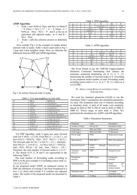
JOURNAL OF EMERGING TECHNOLOGIES IN WEB INTELLIGENCE, VOL. 2, NO. 2, MAY 2010 83APDP Algorithm1 Node v uses N(N(v)) ,N(u), and N(v) to obta<strong>in</strong> P= N (N(u) ∩ N(v) ), U 1 = U – E where U =N(N(v)) – N(u) – N(v) – P and E is the set <strong>of</strong>equivalent and adjacent nodes <strong>in</strong> U and B =N(v) – N(u)2 Node v calls the selection process to determ<strong>in</strong>eF.Now consider Fig 1 <strong>in</strong> the example <strong>of</strong> sample ad-hocnetwork with 12 nodes. Table 1 shows each node <strong>in</strong> Fig 11-hop and 2-hop neighbor nodes. Here we illustrate thedifference between PDP and APDP algorithms.Table 2: PDP algorithmu v P U B FØ 6 Ø 1,3,4,8,10,11 2,5,7,9 7,2,96 7 1,3,6,7 10,12 4,8,11 116 2 2,4,6,8,11 Ø 1,3 [ ]6 9 1,6,9 9 10 107 11 Ø 9 10,12 109 10 Ø 7,12 11 11Table 3: APDP algorithmU V P U B FØ 6 Ø 1,4,8,11 2,5,7,9 7,26 7 1,3,6,7 10,12 4,8,11 116 2 2,4,6,8,11 Ø 1,3 [ ]6 9 1,6,9 9 10 107 11 Ø 9 10,12 109 10 Ø 7,12 11 11The lower bound as per the AMCDS (ApproximationM<strong>in</strong>imum Connected Dom<strong>in</strong>at<strong>in</strong>g Set) reduces them<strong>in</strong>imum connected dom<strong>in</strong>at<strong>in</strong>g set to {2, 6, 7, 11}m<strong>in</strong>imiz<strong>in</strong>g the number <strong>of</strong> forward nodes to 4. Accord<strong>in</strong>gto our proposed model number <strong>of</strong> total forward<strong>in</strong>g nodes<strong>in</strong>clud<strong>in</strong>g source node is 5 i.e. {2, 6, 7, 10, 11} where as itis 6 <strong>in</strong> PDP.Fig 1 An Ad-hoc Network with 12 nodes.Table 1: Two hop neighbors <strong>of</strong> each nodeV N(v) N(N(v))1 1,2,5 1,2,3,5,6,7,92 1,2,3,6,7 1,2,3,4,5,6,7,8,9,113 2,3,4 1,2,3,4,6,7,84 3,4,7,8 2,3,4,6,7,8,11,125 1,5,6,9 1,2,5,6,7,9,106 2,5,6,7,9 1,2,3,4,5,6,7,8,9,10,117 2,4,6,7,8,11 1,2,3,4,5,6,7,8,9,10,11,128 4,7,8,12 2,3,4,6,7,8,11,129 5,6,9,10 1,2,5,6,7,9,10,1110 9,10,11 5,6,7,9,10,11,1211 7,10,11,12 2,4,6,7,8,9,10,11,1212 8,11,12 4,7,8,10,11,12For PDP algorithm, node 6 aga<strong>in</strong> has same forwardnode list F (Ø,6) = [7,2,9]. From P(6,7) = {1,3,6,7 }, wehave U(6,7) = N(N(7)) – N(6) – N(7) – P(6,7) = { 10,12 }.The forward node list for 7 is F(6,7) = {11 }, Similarly ,from P(6,2)= { 2,4,6,8,11} , we have U(6,2) = N(N(2)) –N(6) –N(2) –P(2,6) = Ø and , then , F(6,2) = {10 }.Therefore, the total number <strong>of</strong> forward nodes is 1+3+2 =6. The details <strong>of</strong> P, U, B and F are represented <strong>in</strong> thefollow<strong>in</strong>g Table 2.The total number <strong>of</strong> forward<strong>in</strong>g nodes accord<strong>in</strong>g toPDP is <strong>in</strong> the give example is 6 <strong>in</strong>clud<strong>in</strong>g source node i.e.{ 6,2,7,9,11,10 }.In our proposed model APDP, an enhanced version <strong>of</strong>PDP, the def<strong>in</strong>ition <strong>of</strong> exist<strong>in</strong>g U has been broadened to anew U to check and exclude if it conta<strong>in</strong>s any adjacentnodes. The results <strong>of</strong> the proposed model are presented <strong>in</strong>Table 3IV. SIMULATIONS RESULTS AND SIMULATIONPARAMETERSWe used the simulator glomosim-2.03,[8] to run thesimulation Table 3 summarizes the simulation parameterswe used. The simulation time was 15 m<strong>in</strong>utes accord<strong>in</strong>gto simulator clock. A total <strong>of</strong> 45 nodes were randomlyplaced <strong>in</strong> field <strong>of</strong> 500 X 500 m 2 and <strong>in</strong> field <strong>of</strong> 2000 X2000 m 2 . Power range <strong>of</strong> each node is 250m. Weperformed the simulation for AODV with DP algorithm.Table 3 Simulation ParametersParameter Value DescriptionNumber <strong>of</strong> nodes 160 and 40 Simulation NodesField range x 500m and 2000 X-DimensionField range y 500m and 2000 Y-DimensionPower range 250m Nodes power rangeMac protocol IEEE 802.11 MAC layer protocolNetwork Protocol AODV &RoughAODVTransport Layer UDPProtocolPropagationfunctionFREE-SpaceNetwork LayerTransport LayerPropagationFunctionNode placement Random Nodes aredistributed <strong>in</strong>random mannerSimulation time 15M Accord<strong>in</strong>g tosimulation clockMobility Interval 10-30sec Pause time <strong>of</strong> node© 2010 ACADEMY PUBLISHER