Installing the BayStack 400-ST1 Cascade Module - CXtec
Installing the BayStack 400-ST1 Cascade Module - CXtec
Installing the BayStack 400-ST1 Cascade Module - CXtec

Create successful ePaper yourself
Turn your PDF publications into a flip-book with our unique Google optimized e-Paper software.
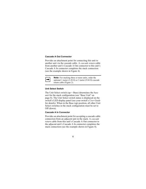
<strong>Cascade</strong> A Out ConnectorProvides an attachment point for connecting this unit toano<strong>the</strong>r unit via <strong>the</strong> cascade cable. A cascade return cablefrom ano<strong>the</strong>r unit’s <strong>Cascade</strong> A Out connector to this unit’s<strong>Cascade</strong> A In connector completes <strong>the</strong> stack connection(see <strong>the</strong> example shown in Figure 4).Note: For stacking three or more units, order <strong>the</strong>optional 1 meter (3.28 ft) or 3 meter (9.84 ft) cascadereturn cable (Figure 2).Unit Select SwitchThe Unit Select switch (up = Base) determines <strong>the</strong> baseunit for <strong>the</strong> stack configuration (see “Base Unit” onpage 8). The Unit Select switch status is displayed on <strong>the</strong>switch’s LED display panel (see your switch’s User Guidefor details). When in <strong>the</strong> Base (up) position, all o<strong>the</strong>r UnitSelect switches in <strong>the</strong> stack configuration must be set toOff (down).<strong>Cascade</strong> A In ConnectorProvides an attachment point for accepting a cascade cableconnection from an adjacent unit in <strong>the</strong> stack. A cascadereturn cable from this unit’s <strong>Cascade</strong> A Out connector to<strong>the</strong> adjacent unit’s <strong>Cascade</strong> A In connector completes <strong>the</strong>stack connection (see <strong>the</strong> example shown in Figure 4).6