


You also want an ePaper? Increase the reach of your titles
YUMPU automatically turns print PDFs into web optimized ePapers that Google loves.
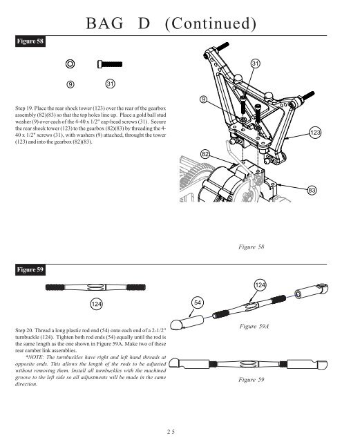
Figure 58BAG D (Co<strong>nt</strong>inued)319 31Step 19. Place the rear shock tower (123) over the rear of the gearboxassembly (82)(83) so that the top holes line up. Place a gold ball studwasher (9) over each of the 4-40 x 1/2" cap-head screws (31). Securethe rear shock tower (123) to the gearbox (82)(83) by threading the 4-40 x 1/2" screws (31), with washers (9) attached, throught the tower(123) and i<strong>nt</strong>o the gearbox (82)(83).98212383Figure 58Figure 5912412454Step 20. Thread a long plastic rod end (54) o<strong>nt</strong>o each end of a 2-1/2"turnbuckle (124). Tighten both rod ends (54) equally u<strong>nt</strong>il the rod isthe same length as the one shown in Figure 59A. Make two of theserear camber link assemblies.*NOTE: The turnbuckles have right and left hand threads atopposite ends. This allows the length of the rods to be adjustedwithout removing them. Install all turnbuckles with the machinedgroove to the left side so all adjustme<strong>nt</strong>s will be made in the samedirection.Figure 59AFigure 5925


