


You also want an ePaper? Increase the reach of your titles
YUMPU automatically turns print PDFs into web optimized ePapers that Google loves.
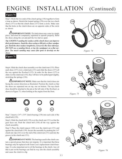
ENGINE INSTALLATION (Co<strong>nt</strong>inued)Figure 74Step 5. Hook the two ends of the clutch spring (156) together to forma loop as shown. Stretch the looped spring (156) over the two clutchshoes (157) so that the clutch shoes (157) form a circle. Make surethat the holes in the clutch shoes are on opposite sides of the circleas shown156IMPORTANT NOTE: Th clutch shoes may come in a singlepiece, and must be completely separated to operate properly. Bendthe shoes along the cut and pull the two halves apart.Tip: LIGHTLY sanding the surface of the clutch shoes can improvetheir performance. Sand the shoes using a 400 grit, or finer sandpaper.Sand the shoe surface lengthwise, not across the shoe sideways.DO NOT use a sanding block, or lay the sandpaper on a flat surface.Too much sanding may cause flat spots to develop on theshoes.Figure 75Figure 74157Step 6. Slide the clutch shoe assembly over the clutch nut (155). Placeeach shoe (157) over a clutch pin (151) and slide the shoes (157) allthe way against the flywheel (152). In order for the shoes (157) toslide over the clutch nut (155), they will have to be pulled apart slightly,stretching the springs (156).IMPORTANT NOTE: Make sure that the clutch shoes arefacing the correct direction as illustrated. Position the clutch so thatthe shoes are separated one on top, one on bottom. The top clutchshoe should be attached to the pin at the left side of the flywheel, asshown in Figure 75, when looking at the engine from the fro<strong>nt</strong>.157Figure 75155156151152Figure 76158 160161Step 7. Insert a 1/4" x 3/8" clutch bearing (158) i<strong>nt</strong>o each side of theclutch bell (159).Step 8. Slide the clutch bell (159) over the clutch nut (151) so that thegear faces out. Push the clutch bell (159) all the way against theclutch assembly.Step 9. Place the clutch spacer (160) over the clutch nut (151) andagainst the clutch bell (159). Secure the assembly by pushing the 1/4"clutch nut clip (161) over the end of the clutch nut (151) and i<strong>nt</strong>o thegroove in the clutch nut (151).160159151IMPORTANT NOTE: The bearings used in the clutch co<strong>nt</strong>aina special grease that does not migrate. It is importa<strong>nt</strong> that thesebearings only be replaced with Team <strong>Losi</strong>'s replaceme<strong>nt</strong> clutch bearings.It is also importa<strong>nt</strong> not to oil the bearings in the clutch. Any oilthat is put on the bearings can find its way i<strong>nt</strong>o the clutch assemblyand cause the clutch to slip.161158158Figure 7633


