


You also want an ePaper? Increase the reach of your titles
YUMPU automatically turns print PDFs into web optimized ePapers that Google loves.
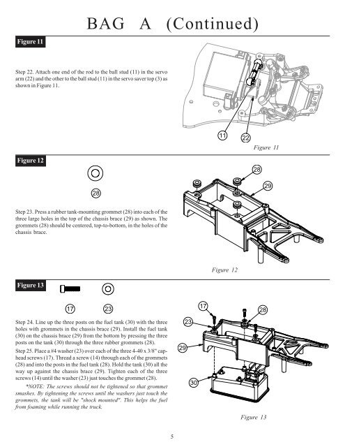
BAG A (Co<strong>nt</strong>inued)Figure 11Step 22. Attach one end of the rod to the ball stud (11) in the servoarm (22) and the other to the ball stud (11) in the servo saver top (3) asshown in Figure 11.11 22Figure 11Figure 12282829Step 23. Press a rubber tank-mou<strong>nt</strong>ing grommet (28) i<strong>nt</strong>o each of thethree large holes in the top of the chassis brace (29) as shown. Thegrommets (28) should be ce<strong>nt</strong>ered, top-to-bottom, in the holes of thechassis brace.Figure 12Figure 1317 231728Step 24. Line up the three posts on the fuel tank (30) with the threeholes with grommets in the chassis brace (29). Install the fuel tank(30) on the chassis brace (29) from the bottom by pressing the threeposts on the tank (30) through the three rubber grommets (28).Step 25. Place a #4 washer (23) over each of the three 4-40 x 3/8" capheadscrews (17). Thread a screw (14) through each of the grommets(28) and i<strong>nt</strong>o the posts in the fuel tank (28). Hold the tank (30) all theway up against the chassis brace (29). Tighten each of the threescrews (14) u<strong>nt</strong>il the washer (23) just touches the grommet (28).*NOTE: The screws should not be tightened so that grommetsmashes. By tightening the screws u<strong>nt</strong>il the washers just touch thegrommets, the tank will be "shock mou<strong>nt</strong>ed". This helps the fuelfrom foaming while running the truck.292330Figure 135


