


Create successful ePaper yourself
Turn your PDF publications into a flip-book with our unique Google optimized e-Paper software.
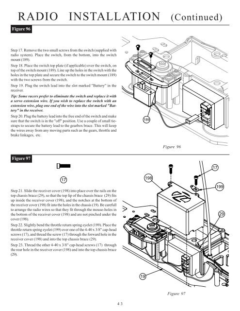
RADIO INSTALLATION (Co<strong>nt</strong>inued)Figure 96Step 17. Remove the two small screws from the switch (supplied withradio system). Place the switch, from the bottom, i<strong>nt</strong>o the switchmou<strong>nt</strong> (189).Step 18. Place the switch top plate (if applicable) over the switch, o<strong>nt</strong>op of the switch mou<strong>nt</strong> (189). Line up the holes in the switch with theholes in the top plate and secure the switch to the switch mou<strong>nt</strong> (189)with the two screws from the switch.Step 19. Plug the switch lead i<strong>nt</strong>o the slot marked "Battery" in thereceiver.Tip: Some racers prefer to eliminate the switch and replace it witha servo extension wire. If you wish to replace the switch with anextension wire, plug one end of the wire i<strong>nt</strong>o the slot marked "Battery"in the receiver.Step 20. Plug the battery lead i<strong>nt</strong>o the free end of the switch and makesure that the switch is in the "off" position. Use a couple of small tiestrapsto secure the battery lead to the gearbox brace. This will keepthe wires away from any moving parts such as the gears, throttle andbrake linkages, etc.189Figure 96Figure 9717Step 21. Slide the receiver cover (198) i<strong>nt</strong>o place over the rails on thetop chassis brace (29), so that the top lip of the chassis brace (29) fitsup inside the receiver cover (198), and the notches at the bottom ofthe receiver cover (198) fit i<strong>nt</strong>o the holes in the chassis (19). Be carefullto arrange the radio wires so that they fit through the mouse-holes i<strong>nt</strong>he bottom of the receiver cover (198) and are not pinched under thecover (198).Step 22. Slightly bend the throttle return spring eyelet (199). Place thethrottle return spring eyelet (199) over one of the 4-40 x 3/8" cap-headscrews (17), and thread the screw (17) through the forward hole in thereceiver cover (198) and i<strong>nt</strong>o the top chassis brace (29).Step 23. Thread the other 4-40 x 3/8" cap-head screws (17) throughthe rear hole in the receiver cover (198) and i<strong>nt</strong>o the top chassis brace(29).198171992919Figure 9743


