

MY1B - SMC
MY1B - SMC
MY1B - SMC
- No tags were found...

Create successful ePaper yourself
Turn your PDF publications into a flip-book with our unique Google optimized e-Paper software.
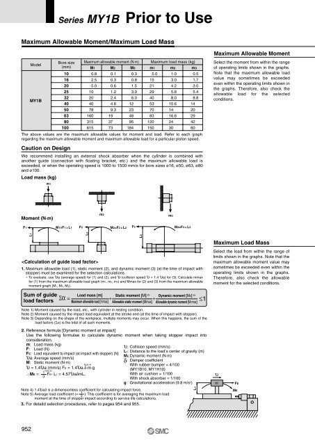
Series <strong>MY1B</strong> Prior to UseMaximum Allowable Moment/Maximum Load MassModel<strong>MY1B</strong>Load mass (kg)Bore size(mm)101620253240506380100Caution on Designm1Maximum allowable moment (N·m)M10.82.55.010204078160315615M20.10.30.61.22.44.89.3193773M30.30.81.53.06.012234895184Maximum load mass (kg)m15.015212940537083120150m21.03.04.25.88.010.61416.62430m30.51.73.05.48.81420294260The above values are the maximum allowable values for moment and load. Refer to each graphregarding the maximum allowable moment and maximum allowable load for a particular piston speed.We recommend installing an external shock absorber when the cylinder is combined withanother guide (connection with floating bracket, etc.) and the maximum allowable load isexceeded, or when the operating speed is 1000 to 1500 mm/s for bore sizes ø16, ø50, ø63, ø80and ø100.Maximum Allowable MomentSelect the moment from within the rangeof operating limits shown in the graphs.Note that the maximum allowable loadvalue may sometimes be exceededeven within the operating limits shown inthe graphs. Therefore, also check theallowable load for the selectedconditions.Moment (N·m)m2m3F1M1=F1 x L1F2M2=F2 x L2F3M3=F3 x L3L1L21. Maximum allowable load (1), static moment (2), and dynamic moment (3) (at the time of impact withstopper) must be examined for the selection calculations.∗ To evaluate, use υa (average speed) for (1) and (2), and υ (collision speed υ = 1.4 υa) for (3). Calculate mmaxfor (1) from the maximum allowable load graph (m1, m2, m3) and Mmax for (2) and (3) from the maximum allowablemoment graph (M1, M2, M3).Sum of guideload factorsΣα = + + ≤1Load mass [m]Maximum allowable load [mmax]L3Static moment [M] (1)Allowable static moment [Mmax]Dynamic moment [ME] (2)Allowable dynamic moment [MEmax]Maximum Load MassSelect the load from within the range oflimits shown in the graphs. Note that themaximum allowable moment value maysometimes be exceeded even within theoperating limits shown in the graphs.Therefore, also check the allowablemoment for the selected conditions.Note 1) Moment caused by the load, etc., with cylinder in resting condition.Note 2) Moment caused by the impact load equivalent at the stroke end (at the time of impact with stopper).Note 3) Depending on the shape of the workpiece, multiple moments may occur. When this happens, the sum of theload factors (Σα) is the total of all such moments.2. Reference formula [Dynamic moment at impact]Use the following formulae to calculate dynamic moment when taking stopper impact intoconsideration.m: Load mass (kg)F: Load (N)FE: Load equivalent to impact (at impact with stopper) (N)υa: Average speed (mm/s)M: Static moment (N·m)Note 4)υ = 1.4υa (mm/s) FE = 1.4υa·δ·m·gNote 5)1∴ME = ·FE· L1 = 4.57υaδmL,3υ: Collision speed (mm/s)L1: Distance to the load , s center of gravity (m)ME:Dynamic moment (N·m)δ: Damper coefficientWith rubber bumper = 4/100(<strong>MY1B</strong>10, MY1H10)With air cushion = 1/100With shock absorber = 1/100g: Gravitational acceleration (9.8 m/s 2 )Note 4) 1.4υaδ is a dimensionless coefficient for calculating impact force.Note 5) Average load coefficient (= 13): This coefficient is for averaging the maximum loadmoment at the time of stopper impact according to service life calculations.3. For detaild selection procedures, refer to pages 954 and 955.L1υmFEME952


