

MY1B - SMC
MY1B - SMC
MY1B - SMC
- No tags were found...

Create successful ePaper yourself
Turn your PDF publications into a flip-book with our unique Google optimized e-Paper software.
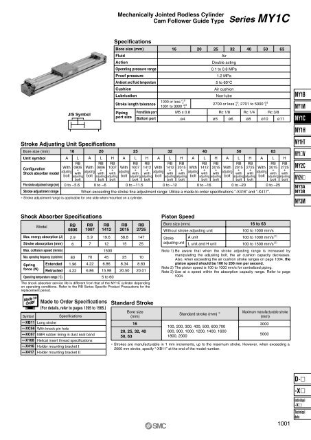
Mechanically Jointed Rodless CylinderCam Follower Guide TypeSeries MY1CStroke Adjusting Unit SpecificationsBore size (mm)Unit symbolConfigurationShock absorber modelFine stroke adjustment range (mm)Stroke adjustment rangeJIS Symbol16 20A L A LWithadjustingboltRB0806+withadjustingboltWithadjustingboltRB0806+withadjustingboltHRB1007+withadjustingboltSpecificationsBore size (mm)FluidActionOperating pressure rangeProof pressureAmbient and fluid temperatureCushionLubricationStroke length tolerancePipingport sizeAWithadjustingboltFront/Side portBottom port25LRB1007+withadjustingboltWithadjustingbolt0 to –5.6 0 to –6 0 to –11.5 0 to –12 0 to –16HA32L16 20 25 32 40 50 63AirDouble acting0.1 to 0.8 MPa1.2 MPa5 to 60°CAir cushionNon-lubeø4 ø5 ø6 ø8 ø10 ø11WithadjustingboltWithadjustingboltWithadjustingboltWhen exceeding the stroke fine adjustment range: Utilize a made-to-order specifications “-X416” and “-X417”.∗ Stroke adjustment range is applicable for one side when mounted on a cylinder.RB1412+withadjustingbolt+1.81000 or less 01001 to 3000 +2.80M5 x 0.8RB1412+withadjustingboltHRB2015+withadjustingboltA40LRB1412+withadjustingbolt+1.8+2.82700 or less 0 , 2701 to 5000 0HRB2015+withadjustingboltRc 1/8 Rc 1/4 Rc 3/8A50LRB2015+withadjustingboltHRB2725+withadjustingboltA630 to –20 0 to –25LRB2015+withadjustingboltHRB2725+withadjustingbolt<strong>MY1B</strong>MY1MMY1CMY1HMY1HTMY1WMY2CMY2HMY3AMY3BMY3MShock Absorber SpecificationsModelRB0806RB1007RB1412RB2015RB2725Max. energy absorption (J)Stroke absorption (mm)Max. collision speed (mm/s)Max. operating frequency (cycle/min)2.96805.977019.61215004558.815251472510Springforce (N)ExtendedRetracted1.964.224.226.866.8615.988.3420.508.8320.01Operating temperature range (°C)5 to 60The shock absorber service life is different from that of the MY1C cylinder dependingon operating conditions. Refer to the RB Series Specific Product Precautions for thereplacement period.Piston SpeedBore size (mm)Without stroke adjusting unitStrokeadjusting unitA unitL unit and H unit16 to 63100 to 1000 mm/s100 to 1000 mm/s100 to 1500 mm/sNote 1) Be aware that when the stroke adjusting range is increased bymanipulating the adjusting bolt, the air cushion capacity decreases.Also, when exceeding the air cushion stroke ranges on page 1004, thepiston speed should be 100 to 200 mm per second.Note 2) The piston speed is 100 to 1000 mm/s for centralized piping.Note 3) Use at a speed within the absorption capacity range. Refer to page1004.(1)(2)Symbol—XB11—XC56—XC67—X168—X416—X417Made to Order Specifications(For details, refer to pages 1395 to 1565.)SpecificationsLong strokeWith knock pin holeNBR rubber lining in dust seal bandHelical insert thread specificationsHolder mounting bracket ΙHolder mounting bracket ΙΙStandard StrokeBore size(mm)1620, 25, 32, 4050, 63Standard stroke (mm) ∗100, 200, 300, 400, 500, 600,700800, 900, 1000, 1200, 1400, 16001800, 2000Maximum manufacturable stroke(mm)∗ Strokes are manufacturable in 1 mm increments, up to the maximum stroke. However, when exceeding a2000 mm stroke, specify “-XB11” at the end of the model number.30005000D-1001-XIndividual-XTechnicaldata


