

MY1B - SMC
MY1B - SMC
MY1B - SMC
- No tags were found...

You also want an ePaper? Increase the reach of your titles
YUMPU automatically turns print PDFs into web optimized ePapers that Google loves.
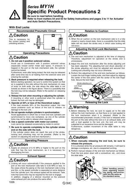
Series MY1HSpecific Product Precautions 2Be sure to read before handling.Refer to front matters 54 and 55 for Safety Instructions and pages 3 to 11 for Actuatorand Auto Switch Precautions.With End LocksRecommended Pneumatic CircuitCautionThis is necessary forthe correct locking andunlocking actions.CautionCautionCautionOperating Precautions1. Do not use 3 position solenoid valves.Avoid use in combination with 3 position solenoid valves(especially closed center metal seal types). If pressure istrapped in the port on the lock mechanism side, the cylindercannot be locked.Furthermore, even after being locked, the lock may be releasedafter some time due to air leaking from the solenoid valve andentering the cylinder.2. Back pressure is required when releasing the lock.Before starting operation, be sure to control the system so thatair is supplied to the side without the lock mechanism (in caseof locks on both ends, the side where the slide table is notlocked) as shown in the figure above. There is a possibility thatthe lock may not be released. (Refer to the section on releasingthe lock.)3. Release the lock when mounting or adjusting the cylinder.If mounting or other work is performed when the cylinder islocked, the lock unit may be damaged.4. Operate at 50% or less of the theoretical output.If the load exceeds 50% of the theoretical output, this maycause problems such as failure of the lock to release, ordamage to the lock unit.5. Do not operate multiple cylinders in synchronization.Avoid applications in which two or more end lock cylinders aresynchronized to move one workpiece, as one of the cylinderlocks may not be able to release when required.6. Use a speed controller with meter-out control.Lock cannot be released occasionally by meter-in control.7. Be sure to operate completely to the cylinder strokeend on the side with the lock.If the cylinder piston does not reach the end of the stroke,locking and unlocking may not be possible. (Refer to thesection on adjusting the end lock mechanism.)Operating Pressure1. Supply air pressure of 0.15 MPa or higher to the port on theside that has the lock mechanism, as it is necessary fordisengaging the lock.Exhaust Speed1. Locking will occur automatically if the pressure applied to theport on the lock mechanism side falls to 0.05 MPa or less. Inthe cases where the piping on the lock mechanism side is longand thin, or the speed controller is separated at some distancefrom the cylinder port, the exhaust speed will be reduced. Takenote that some time may be required for the lock to engage.In addition, clogging of a silencer mounted on the solenoidvalve exhaust port can produce the same effect.1026CautionRelation to Cushion1. When the air cushion on the lock mechanism side is in a fullyclosed or nearly closed state, there is a possibility that the slidetable will not reach the stroke end, in which case locking willnot occur.Adjusting the End Lock MechanismCaution1. The end lock mechanism is adjusted at the time of shipping.Therefore, adjustment for operation at the stroke end isunnecessary.2. Adjust the end lock mechanism after the stroke adjusting unithas been adjusted. The adjusting bolt and shock absorber ofthe stroke adjusting unit must be adjusted and secured first.Locking and unlocking may not occur otherwise.3. Perform fine adjustment of the end lock mechanism as follows.Loosen the lock finger holding bolts, and then adjust by aligningthe center of the lock piston with the center of the lock fingerhole. Secure the lock finger.Lock finger(Hole)Lock pistonStroke adjusting unitWarningCautionReleasing the LockManual ReleasebScrewdriver, etc.aLock fingerLock fingerholding bolt1. Before releasing the lock, be sure to supply air to the sidewithout the lock mechanism, so that there is no load applied tothe lock mechanism when it is released. (Refer to therecommended pneumatic circuits.) If the lock is released whenthe port on the side without the lock is in an exhaust state, andwith a load applied to the lock unit, the lock unit may besubjected to an excessive force and be damaged.Furthermore, sudden movement of the slide table is verydangerous.1. When manually releasing the end lock, be sure torelease the pressure.If it is unlocked while the air pressure still remains, it will lead todamage a workpiece, etc. due to unexpected lurching.2. Perform manual release of the end lock mechanism as follows.Push the lock piston down with a screwdriver, etc., and movethe slide table.Other handling precautionsregarding mounting,piping, and environmentare the same asthe standard series.


