

MY1B - SMC
MY1B - SMC
MY1B - SMC
- No tags were found...

You also want an ePaper? Increase the reach of your titles
YUMPU automatically turns print PDFs into web optimized ePapers that Google loves.
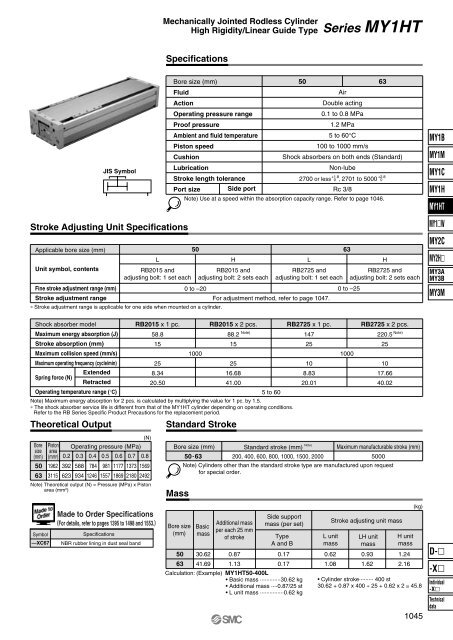
Mechanically Jointed Rodless CylinderHigh Rigidity/Linear Guide TypeSeries MY1HTSpecificationsJIS SymbolBore size (mm)FluidActionOperating pressure rangeProof pressureAmbient and fluid temperaturePiston speedCushionLubricationStroke length tolerancePort size Side port50 63AirDouble acting0.1 to 0.8 MPa1.2 MPa5 to 60°C100 to 1000 mm/sShock absorbers on both ends (Standard)Non-lube+1.8+2.82700 or less 0 , 2701 to 5000 0Rc 3/8Note) Use at a speed within the absorption capacity range. Refer to page 1046.<strong>MY1B</strong>MY1MMY1CMY1HMY1HTStroke Adjusting Unit SpecificationsApplicable bore size (mm)Unit symbol, contentsFine stroke adjustment range (mm)Stroke adjustment rangeLRB2015 andadjusting bolt: 1 set each∗ Stroke adjustment range is applicable for one side when mounted on a cylinder.50 63HRB2015 andadjusting bolt: 2 sets eachLRB2725 andadjusting bolt: 1 set each0 to –20 0 to –25For adjustment method, refer to page 1047.HRB2725 andadjusting bolt: 2 sets eachMY1WMY2CMY2HMY3AMY3BMY3MShock absorber modelMaximum energy absorption (J)Stroke absorption (mm)Maximum collision speed (mm/s)Maximum operating frequency (cycle/min)Spring force (N)ExtendedRetractedRB2015 x 1 pc. RB2015 x 2 pcs. RB2725 x 1 pc. RB2725 x 2 pcs.58.815258.3420.5088.2152516.6841.00Operating temperature range (°C)5 to 60Note) Maximum energy absorption for 2 pcs. is calculated by multiplying the value for 1 pc. by 1.5.∗ The shock absorber service life is different from that of the MY1HT cylinder depending on operating conditions.Refer to the RB Series Specific Product Precautions for the replacement period.Theoretical OutputStandard StrokeNote)147251000 1000108.8320.01220.5251017.6640.02Note)Boresize(mm)5063(N)Piston Operating pressure (MPa)area(mm 2 ) 0.2 0.3 0.4 0.5 0.6 0.7 0.81962 392 588 784 981 1177 1373 15693115 623 934 1246 1557 1869 2180 2492Note) Theoretical output (N) = Pressure (MPa) x Pistonarea (mm 2 )Bore size (mm)Mass50.63Standard stroke (mm) Note)Maximum manufacturable stroke (mm)200, 400, 600, 800, 1000, 1500, 2000 5000Note) Cylinders other than the standard stroke type are manufactured upon requestfor special order.Symbol—XC67Made to Order Specifications(For details, refer to pages 1395 to 1498 and 1553.)SpecificationsNBR rubber lining in dust seal bandBore size(mm)50Basicmass30.62Additional massper each 25 mmof stroke0.87Side supportmass (per set)TypeA and B0.17L unitmass0.62Stroke adjusting unit massLH unitmass0.93H unitmass1.24(kg)D-63 41.69 1.130.17Calculation: (Example) MY1HT50-400L• Basic mass ·············30.62 kg• Additional mass ····0.87/25 st• L unit mass ···············0.62 kg1.081.622.16• Cylinder stroke········· 400 st30.62 + 0.87 x 400 ÷ 25 + 0.62 x 2 ≅ 45.81045-XIndividual-XTechnicaldata


