

MY1B - SMC
MY1B - SMC
MY1B - SMC
- No tags were found...

You also want an ePaper? Increase the reach of your titles
YUMPU automatically turns print PDFs into web optimized ePapers that Google loves.
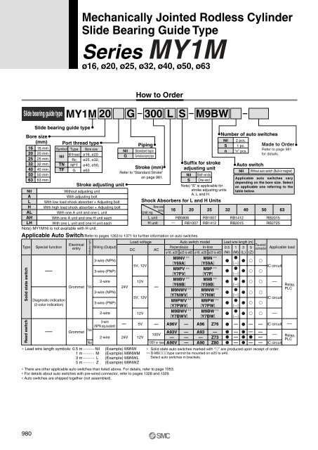
Mechanically Jointed Rodless CylinderSlide Bearing Guide TypeSeries MY1Mø16, ø20, ø25, ø32, ø40, ø50, ø63How to OrderSlide bearing guide typeMY1M20 G 300LSM9BWBore size(mm)16202532405063NilALHALAHLHSlide bearing guide type16 mm20 mm25 mm32 mm40 mm50 mm63 mmPort thread typeSymbol Type Bore sizeNilM thread ø16, ø20Rc ø25, ø32,TNTFNPTGø40, ø50,ø63Stroke adjusting unitWithout adjusting unitWith adjusting boltWith low load shock absorber + Adjusting boltWith high load shock absorber + Adjusting boltWith one A unit and one L unitWith one A unit and one H unit eachWith one L unit and one H unit eachNote) MY1M16 is not available with H unit.NilGPipingStandard typeCentralized piping typeStroke (mm)Refer to “Standard Stroke”on page 981.Number of auto switchesNilSnSuffix for strokeadjusting unitNil Both endsS One endNote) “S” is applicable forstroke adjusting unitsA, L and H.Shock Absorbers for L and H UnitsBore size(mm)Unit no.16 20 25L unitH unit —RB0806RB1007RB1007RB1412Applicable Auto Switch/Refer to pages 1263 to 1371 for further information on auto switches.Solid state switchReed switchIndicator light322 pcs.1 pc.“n” pcs.Auto switchNil Without auto switch (Built-in magnet)RB1412RB201540 50Made to OrderRefer to page 981for details.Applicable auto switches varydepending on the bore size. Selectan applicable one referring to thetable below.RB2015RB2725Type Special functionLoad voltageAuto switch model Lead wire length (m)ElectricalPre-wiredentry Wiring (Output)Perpendicular In-line 0.5 1 3 5DC ACconnectorø16, ø20 ø25 to ø63 ø16, ø20 ø25 to ø63 (Nil) (M) (L) (Z)Applicable loadM9NV ∗∗ M9N ∗∗ 3-wire (NPN)[Y69A] [Y59A][—] 5V, 12VM9PV ∗∗ M9P ∗∗ —3-wire (PNP) [Y7PV] [Y7P][—]IC circuitM9BV ∗∗ M9B ∗∗ 2-wire12V —[Y69B] [Y59B][—]Relay,Grommet Yes24V—M9NWV ∗∗ M9NW ∗∗ PLC3-wire (NPN) [Y7NWV] [Y7NW] [—]5V, 12VDiagnostic indicationM9PWV ∗∗IC circuitM9PW ∗∗ (2-color indication)3-wire (PNP) [Y7PWV] [Y7PW] [—]2-wire12VM9BWV ∗∗ M9BW ∗∗ [Y7BWV] [Y7BW] [—] —3-wire(NPN equivalent)— 5V — A96V — A96 Z76 — — — IC circuit —Yes— GrommetA93V — A93 — — — —100V— Relay,2-wire 24V 12V— — — Z73 — —PLCNo100V or less A90V — A90 Z80 — — — IC circuit∗ Lead wire length symbols: 0.5 m ·········· Nil1 m ·········· M3 m ·········· L(Example) M9NW(Example) M9NWM(Example) M9NWL∗ Solid state auto switches marked with “” are produced upon receipt of order.∗∗ D-M9type cannot be mounted on ø25 to ø40.Select auto switches in brackets.5 m ·········· Z (Example) M9NWZ∗ There are other applicable auto switches than listed above. For details, refer to page 1053.∗ For details about auto switches with pre-wired connector, refer to pages 1328 and 1329.∗ Auto switches are shipped together (not assembled).63980


