

MY1B - SMC
MY1B - SMC
MY1B - SMC
- No tags were found...

You also want an ePaper? Increase the reach of your titles
YUMPU automatically turns print PDFs into web optimized ePapers that Google loves.
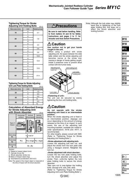
Mechanically Jointed Rodless CylinderCam Follower Guide TypeSeries MY1CTightening Torque for StrokeAdjusting Unit Holding BoltsBore size (mm)16202532405063UnitALALHALHALHALHALHALH(N·m)Tightening torque0.71.83.55.85.813.813.813.827.5PrecautionsBe sure to read before handling. Referto front matters 54 and 55 for SafetyInstructions and pages 3 to 11 forActuator and Auto Switch Precautions.CautionUse caution not to get your handscaught in the unit.• When using a product with strokeadjusting unit, the space between the slidetable (slider) and the stroke adjusting unitbecomes narrow at the stroke end,causing a danger of hands getting caught.Install a protective cover to prevent directcontact with the human body.Adjusting boltLock nutUnit holding boltLock plateholding boltNote) Although the lock plate may slightlybend due to tightening of the lockplate holding bolt, this does not aaffect the shock absorber andlocking function.<strong>MY1B</strong>MY1MMY1CMY1HMY1HTMY1WMY2CMY2HMY3AMY3BTightening Torque for Stroke AdjustingUnit Lock Plate Holding BoltsBore size (mm)Calculation of Absorbed Energyfor Stroke Adjusting Unitwith Shock Absorber(N·m)Type ofimpactKinetic energyE1Thrust energyE2Absorbed energyE253240Horizontalcollisionυ mF·ssUnitLHLHLHVertical(Downward)12υ msm·υ 2(N·m)Tightening torque1.23.33.3103.310Vertical(Upward)sυ mF·s + m·g·s F·s – m·g·sE1 + E2Symbolυ: Speed of impact object (m/s)F: Cylinder thrust (N)s: Shock absorber stroke (m)m: Mass of impact object (kg)g: Gravitational acceleration (9.8 m/s 2 )Note) The speed of the impact object is measured atthe time of impact with the shock absorber.Lock plateCautionShock absorberThe unit can be secured by evenlytightening the four unit holding bolts.Do not operate with the strokeadjusting unit fixed in an intermediateposition.When the stroke adjusting unit is fixed inan intermediate position, slippage canoccur depending on the amount of energyreleased at the time of an impact. In suchcases, the use of the adjusting boltmounting brackets, available per made-toorderspecifications -X416 and -X417, isrecommended.For other lengths, please consult with <strong>SMC</strong>(Refer to “Tightening Torque for StrokeAdjusting Unit Holding Bolts”.)Loosen the adjusting bolt lock nut, andadjust the stroke from the lock plate sideusing a hexagon wrench. Retighten thelock nut.Loosen the two lock plate holding bolts,turn the shock absorber and adjust thestroke. Then, uniformly tighten the lockplate holding bolts to secure the shockabsorber.Take care not to over-tighten the holdingbolts. (Except ø16, ø20, ø50, ø63)(Refer to “Tightening Torgue for StrokeAdjusting Unit Lock Plate Holding Bolts”.)1005MY3MD--XIndividual-XTechnicaldata


