

MY1B - SMC
MY1B - SMC
MY1B - SMC
- No tags were found...

You also want an ePaper? Increase the reach of your titles
YUMPU automatically turns print PDFs into web optimized ePapers that Google loves.
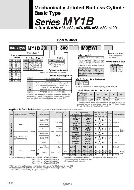
Mechanically Jointed Rodless CylinderBasic TypeSeries <strong>MY1B</strong>ø10, ø16, ø20, ø25, ø32, ø40, ø50, ø63, ø80, ø100How to OrderBasic typeBore size(mm)10162025324050638010010 mm16 mm20 mm25 mm32 mm40 mm50 mm63 mm80 mm100 mm<strong>MY1B</strong> 20 300Basic typePort thread typeSymbol Type Bore sizeNilM thread ø10, ø16, ø20Rc ø25, ø32, ø40,TNTFNPTGø50, ø63, ø80,ø100NilALHALAHLHPipingStandard typeCentralized piping typeNilGNote) For ø10, only G isavailable.Cylinder stroke (mm)Refer to “Standard Stroke” on page 957.Stroke adjusting unitWithout adjusting unitWith adjusting boltWith low load shock absorber + Adjusting boltWith high load shock absorber + Adjusting boltWith one A unit and one L unitWith one A unit and one H unit eachWith one L unit and one H unit eachOnly the A unit is available for ø16. Stroke adjusting unit is notavailable for ø50, ø63, ø80 and ø100. For detailed informationon stroke adjusting unit specifications, refer to page 957.M9BWAuto switchNil Without auto switch (Built-in magnet)For ø10 cylinders without an autoswitch, the cylinder configuration is forthe reed auto switch.Contact <strong>SMC</strong> when the solid state autoswitch is retrofitted.Applicable auto switches varydepending on the bore size. Selectan applicable one referring to thetable below.Suffix for stroke adjusting unitNil Both sidesS One sideNote) “S” is applicable for stroke adjusting units A, L and H.Shock Absorbers for L and H UnitsBore size(mm)Unit no.L unitH unit10—RB080520RB0806RB100725RB1007RB1412Made to OrderRefer to page 957for details.Number of autoswitchesNilSn322 pcs.1 pc.“n” pcs.RB1412RB2015The shock absorber service life is different from that of the <strong>MY1B</strong> cylinderdepending on operating conditions. Refer to the RB Series SpecificProduct Precautions for the replacement period.40Applicable Auto Switch/Refer to pages 1263 to 1371 for further information on auto switches.Type Special functionLoad voltageAuto switch model Lead wire length (m)ElectricalPre-wiredentry Wiring (Output)Perpendicular In-line 0.5 1 3 5DC ACconnectorø10 to ø20 ø25 to ø100 ø10 to ø20 ø25 to ø100 (Nil) (M) (L) (Z)Applicable loadM9NV ∗∗ M9N ∗∗ 3-wire (NPN)[Y69A] [Y59A][—] 5V, 12VM9PV ∗∗ M9P ∗∗ —3-wire (PNP) [Y7PV] [Y7P][—]IC circuitM9BV ∗∗ M9B ∗∗ 2-wire12V —[Y69B] [Y59B][—]Relay,Grommet Yes24V—M9NWV ∗∗ M9NW ∗∗ PLC3-wire (NPN) [Y7NWV] [Y7NW] [—]5V, 12VDiagnostic indicationM9PWV ∗∗IC circuitM9PW ∗∗ (2-color indication)3-wire (PNP) [Y7PWV] [Y7PW] [—]2-wire12VM9BWV ∗∗ M9BW ∗∗ [Y7BWV] [Y7BW] [—] —3-wire(NPN equivalent)— 5V — A96V — A96 Z76 — — — IC circuit ——YesGrommetA93V — A93 — — — —100V— Relay,2-wire 24V 12V— — — Z73 — —PLCNo100V or less A90V — A90 Z80 — — — IC circuit∗ Lead wire length symbols: 0.5 m ·········· Nil1 m ·········· M3 m ·········· L(Example) M9NW(Example) M9NWM(Example) M9NWL∗ Solid state auto switches marked with “” are produced upon receipt of order.∗∗ D-M9type cannot be mounted on ø50.Select auto switches in brackets.5 m ·········· Z (Example) M9NWZ∗ There are other applicable auto switches than listed above. For details, refer to page 1053.∗ For details about auto switches with pre-wired connector, refer to pages 1328 and 1329.∗ Auto switches are shipped together (not assembled).Solid state switchReed switchIndicator light956


