

MY1B - SMC
MY1B - SMC
MY1B - SMC
- No tags were found...

You also want an ePaper? Increase the reach of your titles
YUMPU automatically turns print PDFs into web optimized ePapers that Google loves.
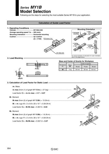
Series <strong>MY1B</strong>Model SelectionFollowing are the steps for selecting the most suitable Series <strong>MY1B</strong> to your application.Calculation of Guide Load Factor1. Operating ConditionsCylinder ······································· <strong>MY1B</strong>32-500Average operating speed υa ···· 300 mm/sMounting orientation ··················Horizontal mountingCushion ······································· Air cushion(δ = 1/100)W: Workpiece (2 kg)1. HorizontalmountingxMounting Orientationzy2. WallmountingP. 948xyz3. CeilingmountingP. 998xy4. VerticalmountingP. 1042zxy<strong>MY1B</strong>32-500z2. Load BlockingFor actual examples of calculation for each orientation,refer to the pages above.YMass and Center of Gravity for WorkpieceZ20XWorkpieceno.WMassm2 kgX-axis20 mmCenter of gravityY-axis30 mmZ-axis50 mm50Y303. Calculation of Load Factor for Static Loadm1: Massm1 max (from (1) of graph <strong>MY1B</strong>/m1) = 27 (kg)················································m1Load factor α1 = m1/m1 max = 2/27 = 0.07M1: MomentM1 max (from (2) of graph <strong>MY1B</strong>/M1) = 13 (N·m)············································································m1XM1 = m1 x g x X = 2 x 9.8 x 20 x 10 –3 = 0.39 (N·m)Load factor α2 = M1/M1 max = 0.39/13 = 0.03M1M2: MomentM2 max (from (3) of graph <strong>MY1B</strong>/M2) = 1.6 (N·m)·········································································YM3 = m1 x g x Y = 2 x 9.8 x 30 x 10 –3 = 0.59 (N·m)m1Load factor α3 = M2/M2 max = 0.59/1.6 = 0.37M2954


