

MY1B - SMC
MY1B - SMC
MY1B - SMC
- No tags were found...

You also want an ePaper? Increase the reach of your titles
YUMPU automatically turns print PDFs into web optimized ePapers that Google loves.
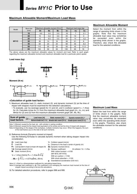
Series MY1C Prior to UseMaximum Allowable Moment/Maximum Load MassModelMY1CBore size(mm)16202532405063Maximum allowable moment (N·m)M16.010153060115150M23.05.08.514233550M32.03.05.010203550Maximum load mass (kg)m1182535496893130m27101421304260m32.134.268.211.516The above values are the maximum allowable values for moment and load. Refer to each graphregarding the maximum allowable moment and maximum allowable load for a particular piston speed.Maximum Allowable MomentSelect the moment from within therange of operating limits shown in thegraphs. Note that the maximumallowable load value may sometimesbe exceeded even within theoperating limits shown in the graphs.Therefore, also check the allowableload for the selected conditions.Load mass (kg)m1Moment (N·m)m2m3F1M1=F1 x L1F2M2=F2 x L2F3M3=F3 x L3L1L2L31. Maximum allowable load (1), static moment (2), and dynamic moment (3) (at the time ofimpact with stopper) must be examined for the selection calculations.∗ To evaluate, use υa (average speed) for (1) and (2), and υ (collision speed υ = 1.4υa)for (3). Calculate mmax for (1) from the maximum allowable load graph (m1, m2, m3) andMmax for (2) and (3) from the maximum allowable moment graph (M1, M2, M3).Sum of guideload factorsΣα = + + ≤ 1Load mass [m]Maximum allowable load [m max]Static moment [M] (1)Allowable static moment [Mmax]Dynamic moment [ME] (2)Allowable dynamic moment [MEmax]Note 1) Moment caused by the load, etc., with cylinder in resting condition.Note 2) Moment caused by the impact load equivalent at the stroke end (at the time of impact with stopper).Note 3) Depending on the shape of the workpiece, multiple moments may occur. When this happens, the sumof the load factors (∑α) is the total of all such moments.Maximum Load MassSelect the load from within the rangeof limits shown in the graphs. Notethat the maximum allowable momentvalue may sometimes be exceededeven within the operating limits shownin the graphs. Therefore, also checkthe allowable moment for the selectedconditions.2. Reference formula [Dynamic moment at impact]Use the following formulae to calculate dynamic moment when taking stopper impact intoconsideration.m: Load mass (kg)υ: Collision speed (mm/s)F: Load (N)L1: Distance to the load , s center of gravity (m)FE: Load equivalent to impact (at impact with stopper) (N) ME: Dynamic moment (N·m)υa: Average speed (mm/s)δ : Damper coefficient At collision: υ = 1.4υaM: Static moment (N·m)With rubber bumper = 4/100Note 4) (<strong>MY1B</strong>10, MY1H10)υ = 1.4υa (mm/s) FE = 1.4υa·δ·m·gWith air cushion = 1/100Note 5)1∴ME = ·FE·L1 = 4.57υaδmL1 (N·m) With shock absorber = 1/1003g: Gravitational acceleration (9.8 m/s 2 )Note 4) 1.4υaδ is a dimensionless coefficient for calculating impact force.1Note 5) Average load coefficient (= 3): This coefficient is for averaging the maximum load moment at the time ofstopper impact according to service life calculations.3. For detailed selection procedures, refer to pages 998 and 999.L1υmFEME996


